
Support Substrate for Separation Membrane

a technology of support substrate and separation membrane, which is applied in the direction of synthetic resin layered products, textiles and paper, woven fabrics, etc., can solve the problems of increasing the risk of tearing through, affecting the treatment efficiency of the substrate, and affecting the effect of the separation membrane, so as to achieve excellent strike-through prevention

Active Publication Date: 2008-06-12
ASAHI KASEI FIBERS CORPORATION
View PDF3 Cites 25 Cited by
  • Summary
  • Abstract
  • Description
  • Claims
  • Application Information

AI Technical Summary

Benefits of technology

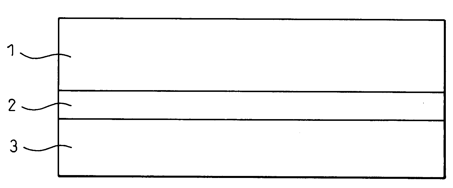
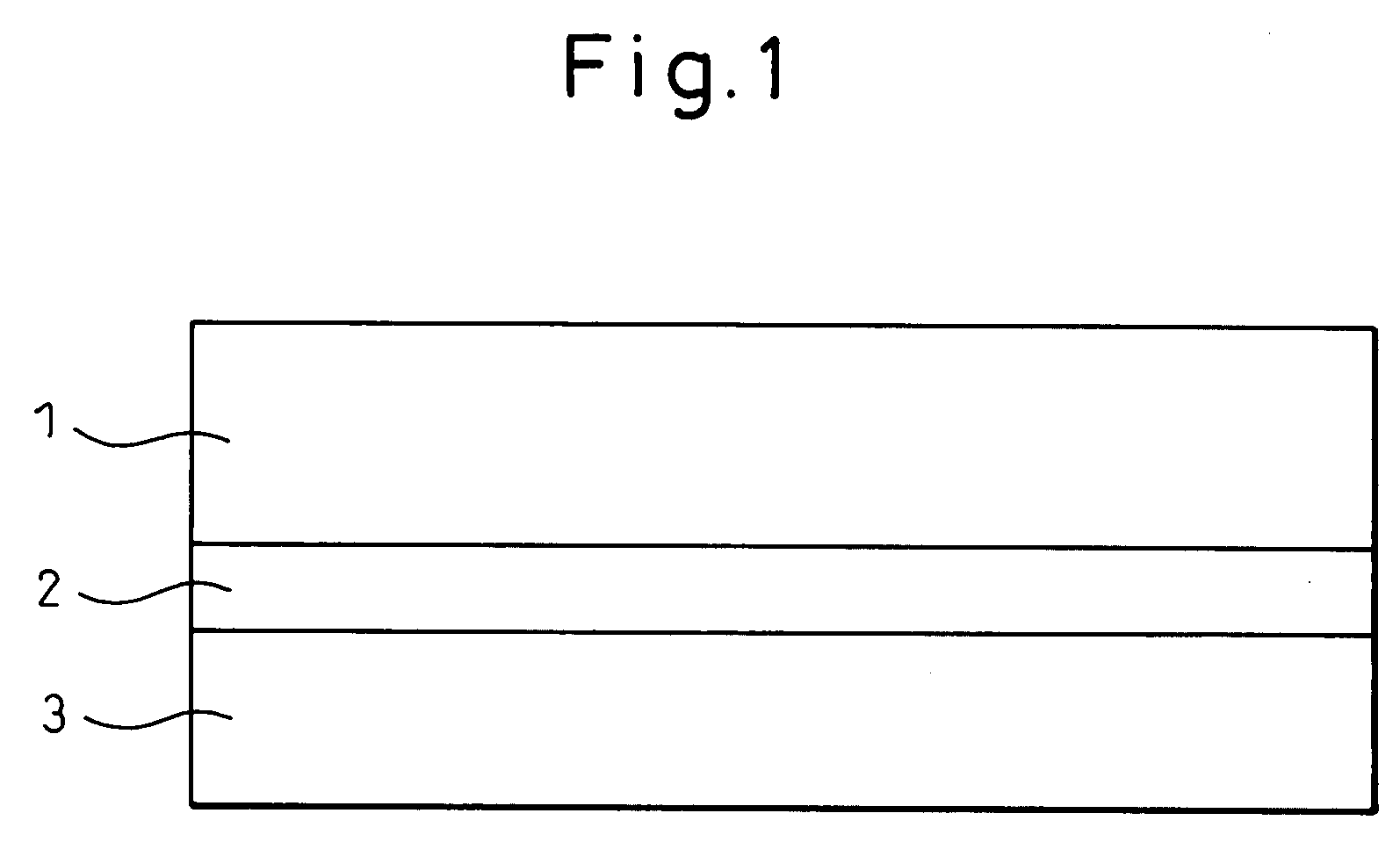
[0042]The separation membrane support substrate of the invention is composed of a laminated nonwoven fabric wherein a small amount of melt blown fibers (middle layer) are laminated and heat bonded between thermoplastic resin filament nonwoven fabrics as the front layer and back layer. In a laminated nonwoven fabric having this structure, the apparent density is set within a specific range in order to achieve the opposing properties of adhesion with coating resins and strike-through prevention, thereby allowing high strength to be achieved, even with thin nonwoven fabrics with low amounts of fibers.
[0088]Moreover, although the reason is not fully understood, it was surprisingly found that using a resin with a relatively high melting point as the thermoplastic resin for the melt blown fibers better facilitates penetration of the melt blown fibers. Thus, it is preferred to use a resin with a high melting point of 180° C. or above, such as PET or polyamide, as the thermoplastic resin. Also, a crystallinity of 15-40% for the melt blown fibers is preferred for more satisfactory adhesion and penetration.

Problems solved by technology

In recent years, as such separation membranes have become more widely used, an improvement in treatment efficiency, per cartridge, has also become an important issue.
However, when the amount of fiber is reduced to form a thinner support substrate, the problem of “strike-through” can occur whereby the resin seeps out from the back of the support substrate during coating.
The resin escaping from the back side of the support substrate contaminates the film-forming apparatus and can cause defects in a continuously formed separation membrane.
Also, although reducing the amount of fiber to form a thinner support substrate increases the liquid permeability, it also results in noticeable thickness spots in the support substrate and more sections susceptible to “strike-through”.
Another serious problem is reduced strength and, particularly in the case of a staple fiber wet laid nonwoven fabric, reducing the amount of fiber results in a drastic reduction in strength.
However, for the reasons explained above, the strength is significantly low when the fiber diameter is 4.5 μm or smaller and, therefore, it has not been possible to sufficiently achieve a thinner size while preventing strike-through.
US2005-6301 describes a method of mixing staple fibers with different fiber lengths, but it is not possible to obtain a thin support substrate having sufficiently high strength while preventing strike-through.
However, a dense layer composed of thin fibers has a high L / D ratio and therefore the fibers tend to tangle together during wet laid, and the obtained nonwoven fabric is susceptible to defects such as projections.
However, the obtained support substrate cannot be satisfactory because of increased thickness.
Even by this method, however, the problem of unevenness is not eliminated in the staple fiber dry method.
Consequently, the thickness of the support substrate is increased and a thin support substrate cannot be satisfactorily achieved.
However, problems with nonwoven fabrics having the former structure include weak bonding conditions in 50 wt % or more of the fibers, and wrinkles during the separation membrane production process due to a lack of strength or low rigidity.
Because of weak bonding on the coating side, fluffing tends to occur upon contact with the guide roll in the resin coating step, leading to poor stability during resin coating.
A problem with nonwoven fabrics having the latter structure is that the valleys having high fiber density are resistant to penetration and the coating resin preferentially penetrates into the hills, such that the coating resin reaches the tops of the hills before penetrating to the valleys, therefore resulting in a non-uniform coating.
In order to avoid these problems, some supports are produced by lamination with perforated nonwoven fabrics or nonwoven fabrics with hill-valley forms produced by a separate step such as corrugation, but in such cases the hills and valleys cause thickness spots in the resin coating layer, resulting in reduced stability of the membrane performance.

Method used


Image

  • Support Substrate for Separation Membrane
  • Support Substrate for Separation Membrane

Examples


examples 1-14 , 18

EXAMPLES 1-14, 18, COMPARATIVE EXAMPLES 2, 4-6, 8-12

[0139]As the back layer, ordinary PET was used for extrusion toward a filament group-shifting collecting net, and spinning was carried out by a spun bond method at a spinning temperature of 300° C., at a spinning speed of 3500 m / min, after which the filaments were sufficiently opened by corona charging to about 3 μC / g, to prepare a thermoplastic resin filament web on the collecting net. The filament diameter was adjusted by changing the discharge volume.

[0140]Next, for the middle layer, PET (solution viscosity: ηsp / c=0.50) was used for spinning by a melt blow method under conditions with a spinning temperature of 300° C. and heated air at 1000 Nm3 / hr / m, and blowing onto the thermoplastic resin filament web. Here, the distance from the melt blow nozzle to the thermoplastic resin filament web was 100 mm, the suction force on the collecting surface directly under the melt blow nozzle was 0.2 kPa, and the air speed was 7 m / sec. The fib...

example 15

[0147]A laminated nonwoven fabric having a thermoplastic resin filament / melt blown fiber / thermoplastic resin filament structure was obtained in the same manner as Example 1. However, the heat bonding conditions with the flat roll were a line pressure of 367 N / cm and a roll temperature of 225° C. on the surface side (coating side) and 215° C. on the back side.

[0148]The support made of the obtained laminated nonwoven fabric and its evaluation results are shown in Tables 1 and 2.

example 16

[0149]A laminated nonwoven fabric was obtained in the same manner as Example 1, except that the calender roll temperature was 231° C. for both the surface and back sides, and the line pressure was 570 N / cm. The surface smoothness of the support substrate composed of the obtained laminated nonwoven fabric is shown in Table 3 together with the surface smoothness of the support substrate obtained in Example 1.

[0150]The surface of Example 1 had excellent smoothness. For Example 16, some streaks were apparent due to fine irregularities in the coating surface, but the surface smoothness was satisfactory and no significant problems were encountered in coating.


PUM

PropertyMeasurementUnit
diameteraaaaaaaaaa
diameteraaaaaaaaaa
diameteraaaaaaaaaa

Abstract

A separation membrane support substrate characterized by being composed of a laminated nonwoven fabric comprising a front layer as the resin coating layer, a middle layer and a back layer which are integrally formed by heat bonding, and by satisfying the following conditions (1) to (5): (1) The front layer has at least one layer comprising thermoplastic resin filaments with a single filament diameter of 7-30 μm; (2) the middle layer has at least one layer comprising melt blown fibers with a single fiber diameter of no greater than 5 μm, and a fiber basis weight of at least 1 g / m2 and comprising no more than 30 wt % of the total fiber basis weight; (3) the back layer has at least one layer comprising thermoplastic resin filaments with a single filament diameter of 7-20 μm, and has a fiber basis weight of 3-40 g / m2; (4) the laminated nonwoven fabric has an apparent density of 0.67-0.91 g / cm3; and (5) the laminated nonwoven fabric has a thickness of 45-110 μm.

Description

TECHNICAL FIELD[0001]The present invention relates to a support substrate for a separation membrane such as an ultrafiltration membrane or reverse osmosis membrane.BACKGROUND ART[0002]Filters used for ultrafiltration and reverse osmosis include spiral types wherein a flat separation membrane is coiled in spiral fashion, types wherein a plurality of hollow fiber separation membranes are arranged in parallel and tubular types wherein a flat separation membrane is worked into a cylindrical shape, and all such types can be held in a cartridge with a fixed volume for use.[0003]Among such separation membranes, the flat separation membranes are produced as sheets by coating a resin with a separating function onto a support substrate such as a nonwoven fabric. The nonwoven fabric used as the support substrate functions as a coating base for production of a uniform film when the separation membrane is produced, while also performing the basic function of strength maintenance to prevent ruptu...

Claims


Application Information

Patent Timeline
Patent Type & Authority Applications(United States)
IPC IPC(8): D04H1/54B01D69/10B01D71/48D04H3/16B32B5/26D06C15/00
CPCB01D39/163B32B2307/72B01D2239/0208B01D2239/0216B01D2239/0668B32B5/26D04H13/007B32B5/022B32B7/02B32B2250/03B32B2255/02B32B2255/26B32B2262/0276B32B2262/0284B32B2307/54B32B2307/718B01D69/10Y10T442/659Y10T442/697Y10T442/62Y10T442/671Y10T442/614Y10T442/66B01D69/1071B01D71/48B32B5/265B01D69/1216D04H3/14B01D2239/1233B01D2239/0622
Inventor YOSHIDASUZUKA, RYUJI
Owner ASAHI KASEI FIBERS CORPORATION
Learn More