Laminated layer fuel cell and method for manufacturing the same

a fuel cell and laminate technology, applied in the direction of cell components, final product manufacturing, sustainable manufacturing/processing, etc., can solve the problems of insufficient gaseous diffusion performance and inability to restraining impregnation, and achieve the effects of lowering gaseous diffusion performance, reducing viscosity, and high outpu

Inactive Publication Date: 2008-06-12
NORITAKE CO LTD
View PDF5 Cites 15 Cited by
  • Summary
  • Abstract
  • Description
  • Claims
  • Application Information

AI Technical Summary

Benefits of technology

[0017]These provide high density of the electrode layer accompanied with the catalyst layer in the first aspect of the present invention and of the base material for an electrode accompanied with the catalyst layer in the second aspect of the present invention, by the above described range of amounts of air flow permeation in the thickness direction in the dried state. Accordingly, impregnation into the electrode layer or the base material for an electrode (hereinafter, both referred to as the electrode layer if distinction is not required) is preferably restrained upon forming the electrolyte layer by application of the electrolyte solution on one side. This provides the laminated layer fuel cell with high output since impregnated electrolyte restrains lowering in the gaseous diffusion performance and the reactivity with catalyst of the electrode layer. The above range of amount of air flow permeation of the electrode layer accompanied with the catalyst layer is required because the amount of below 10000 ml·m / cm2 / min causes insufficient gaseous diffusion performance irrespective of impregnation of the electrolyte solution, and the amount of over 12000 ml·m / cm2 / min causes incapability of restraining of impregnation of the electrolyte solution.
[0019]The object indicated above may be achieved according to a third aspect of the invention, which provides the method according to the second aspect of the invention, wherein the gaseous diffusion electrode layer is formed in heat treatment of slurry including carbon fibers, conductive polymer and thermosetting resin, at or below 200° C. This provides the laminated layer fuel cell with higher output by higher current density.
[0020]The object indicated above may be achieved according to a fourth aspect of the invention, which provides the method according to the second or third aspect of the invention, wherein the electrolyte solution has viscosity in the range of 600 to 1000 mPa·s. This provides the laminated layer fuel cell with further higher output by further restraining of impregnation into the electrode layer with viscosity in the preferred range. The electrolyte solution having over 600 mPa·s in viscosity is preferred for further restraining impregnation, irrespective of the electrolyte having the amount of air permeation in the above disclosed range. The electrolyte solution having the viscosity of over 1000 mPa·s prevents application of the solution in uniform thickness on the surface of the catalyst layer due to its excessive high viscosity.
[0025]Preferably, the air flow permeation rate may be determined in a range of 10000 to 12000 ml·m / cm2 / min in the first and second aspects of the invention. This causes further higher output by further restraint of lowering in gaseous diffusion performance due to further restraint of impregnation of the electrolyte solution.
[0026]Preferably, the electrolyte solution may be regulated in concentration in the range of 32-35%. This causes preferable restraint of impregnation of the electrolyte solution into the electrode layer by its viscosity described above, due to regulation in concentration in an appropriate range for the electrolyte solution. The concentration of the solution is preferably not less than 32% to restrain impregnation of the electrolyte solution since lower concentration of the solution causes lower viscosity. The concentration of the solution is preferably not more than 35% to provide sufficient uniformity in the formed membrane since higher concentration of the solution causes higher viscosity.

Problems solved by technology

The above range of amount of air flow permeation of the electrode layer accompanied with the catalyst layer is required because the amount of below 10000 ml·m / cm2 / min causes insufficient gaseous diffusion performance irrespective of impregnation of the electrolyte solution, and the amount of over 12000 ml·m / cm2 / min causes incapability of restraining of impregnation of the electrolyte solution.

Method used


Image

  • Laminated layer fuel cell and method for manufacturing the same
  • Laminated layer fuel cell and method for manufacturing the same
  • Laminated layer fuel cell and method for manufacturing the same

Examples


Embodiment Construction

[0044]Hereinafter, there will be described the present invention by reference to the drawings. The figures are appropriately simplified or transformed, and all the proportion of the dimension and the shape of a portion or member may not be reflective of the real one in the following embodiments.

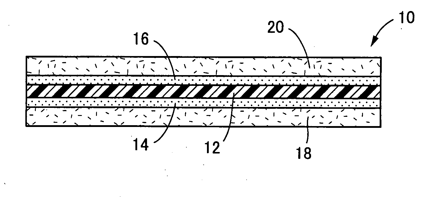
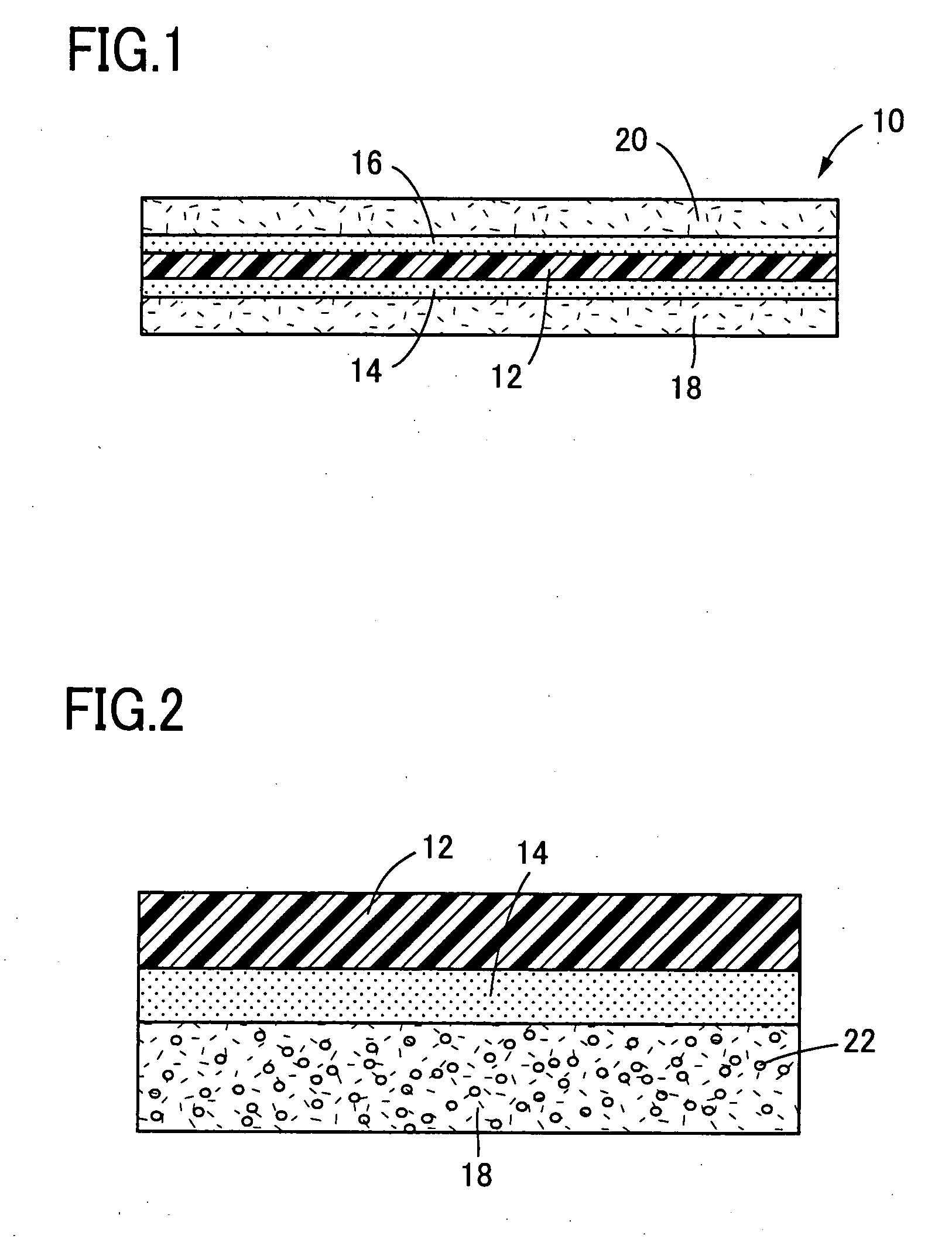
[0045]FIG. 1 illustrates a membrane electrode assembly (MEA) 10 of a plate type in a cross sectional view according to an embodiment of the present invention. The MEA 10 includes a thin layer of an electrolyte membrane 12 that expands as a plate, catalyst layers 14, 16, and gaseous diffusion electrodes 18, 20. The catalyst layers 14, 16 are respectively disposed on each surface of the electrolyte membrane 12, and the gaseous diffusion electrodes 18, 20 are respectively disposed on each surface of the catalyst layers 14, 16 as shown in FIG. 1. That is, the electrolyte membrane 12 is interposed between the catalyst layers 14, 16, and a set of the electrolyte membrane 12 and the catalyst layers ...


PUM

PropertyMeasurementUnit
viscosityaaaaaaaaaa
temperatureaaaaaaaaaa
diameteraaaaaaaaaa

Abstract

A laminated layer fuel cell includes a solid polymer electrolyte layer, a pair of catalyst layers, and a pair of gaseous diffusion electrode layers, one of the pair of catalyst layers and one of the pair of gaseous diffusion electrode layers being formed on one side of the solid polymer electrolyte layer, and the other of the pair of catalyst layers and the other of the pair of gaseous diffusion electrode layers being formed on the other side of the solid polymer electrolyte layer, wherein the one of the pair of catalyst layers and the one of the pair of the gaseous diffusion electrode layers constitute a composite electrode layer, and the composite electrode layer has an amount in a range of 10000 to 12000 ml·mm / cm2 / min of air flow permeation in the thickness direction in a dried state.

Description

[0001]This application is based on Japanese Patent Application No. 2006-307111 filed Nov. 13, 2007, the contents of which are incorporated hereinto by reference.BACKGROUND OF THE INVENTION[0002]1. Field of the Invention[0003]The present invention relates to a laminated layer fuel cell of which electrolyte layers are made of solid polymer material, and a method for manufacturing the same.[0004]2. Description of Related Art[0005]Fuel cells are electrochemical devices that convert chemical energy in fuels into electrical energy directly. In the fuel cells the fuels of reductants such as reformed hydrogen manufactured from hydrogen, methanol or fossil fuel are electrochemically oxidized by oxidants such as air or oxygen. They draw attention recently and are expected to be “clean” (namely, producing relatively little pollutant) sources of electrical energy that provide power in higher conversion efficiency than internal engines in silence and with minimal pollutant such as NOx, SOx and p...

Claims


Application Information

Patent Timeline
Patent Type & Authority Applications(United States)
IPC IPC(8): H01M8/10B05D3/00
CPCH01M4/8605H01M4/8828H01M8/0234H01M8/0239Y02E60/521H01M8/1023H01M8/1039H01M8/1058H01M8/1081H01M8/0243Y02P70/50Y02E60/50
Inventor YOSHIKAWA, DAISHI
Owner NORITAKE CO LTD
Why Eureka
Try Eureka