Gas Generator and Method of Manufacturing the Same
- Summary
- Abstract
- Description
- Claims
- Application Information
AI Technical Summary
Benefits of technology
Problems solved by technology
Method used
Image

Examples
Embodiment Construction
[0032]A gas generator according to a first embodiment of the present invention will be described below with reference to the accompanying drawings.
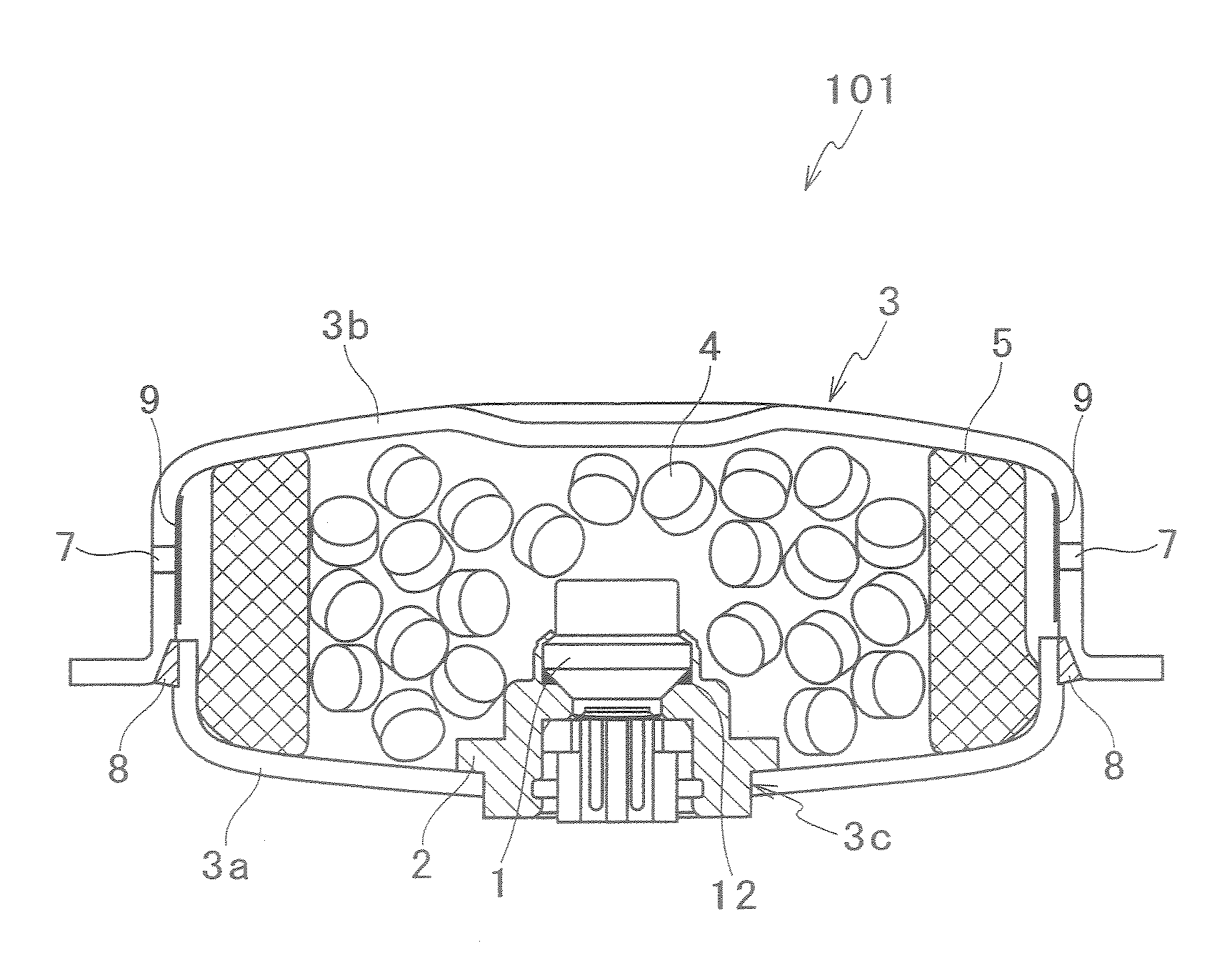
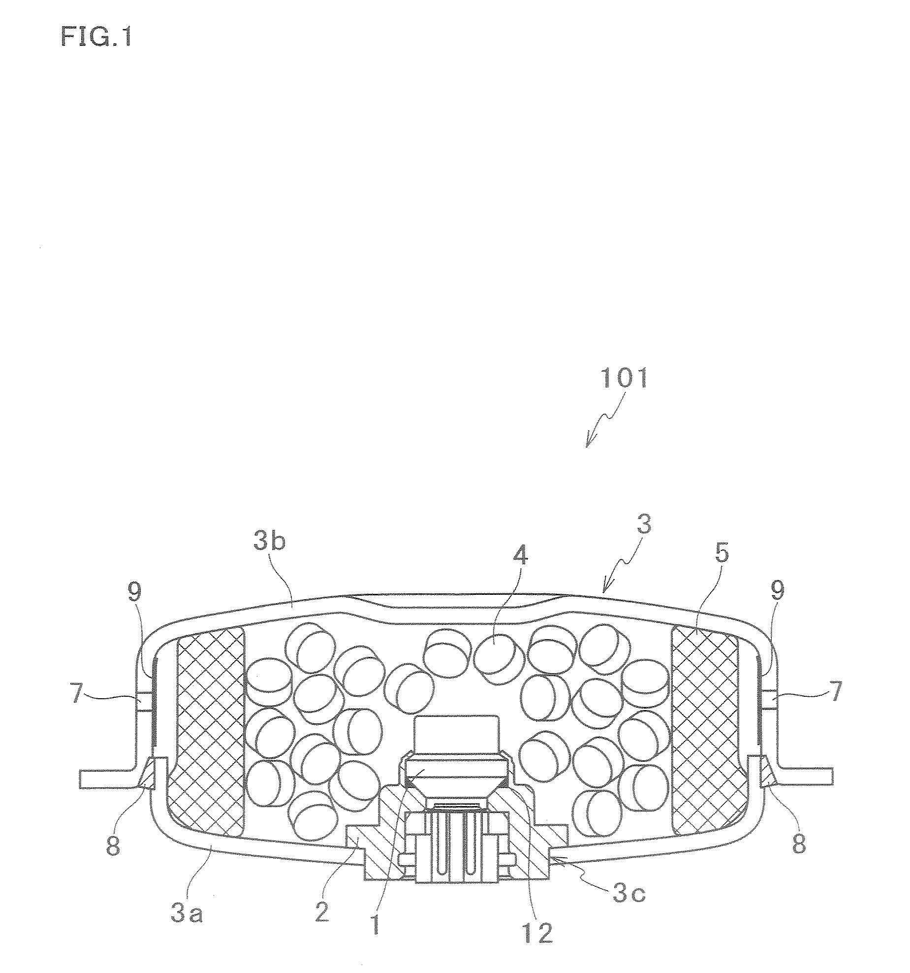
[0033]FIG. 1 is a cross sectional view of a gas generator 101 which is an example of the gas generator of the present invention. In FIG. 1, the gas generator 101, which inflates and deploys, for example, a driver seat airbag, includes an approximately short cylindrical housing 3 including a bottomed member 3a and a lid member 3b, gas generants 4 which are arranged in the housing 3 to generate a high-temperature gas by combustion, a filter 5 which is arranged in an inner circumference part of the housing 3 so as to surround the gas generants 4 in a diameter direction of the housing 3, an igniter 1 which is energized from the outside to ignite, and a holder 2 to which the igniter 1 is fixed and which is fixed to the bottomed member 3a so that the igniter 1 is arranged coaxially with the housing 3.
[0034]The lid member 3b has a cylindrical pa...
PUM
| Property | Measurement | Unit |
|---|---|---|
| Diameter | aaaaa | aaaaa |
| Strength | aaaaa | aaaaa |
Abstract
Description
Claims
Application Information
 - Generate Ideas
- Intellectual Property
- Life Sciences
- Materials
- Tech Scout
- Unparalleled Data Quality
- Higher Quality Content
- 60% Fewer Hallucinations
Browse by: Latest US Patents, China's latest patents, Technical Efficacy Thesaurus, Application Domain, Technology Topic, Popular Technical Reports.
© 2025 PatSnap. All rights reserved.Legal|Privacy policy|Modern Slavery Act Transparency Statement|Sitemap|About US| Contact US: help@patsnap.com