Printhead substrate, printhead, and printing apparatus

a printing apparatus and substrate technology, applied in printing and other directions, can solve the problems of increased number of scans needed for printing, increased production difficulty, and inconvenient printing, and achieve the effects of high printing speed, high density, and high printing quality

Active Publication Date: 2008-06-19
CANON KK
View PDF8 Cites 3 Cited by
  • Summary
  • Abstract
  • Description
  • Claims
  • Application Information

AI Technical Summary

Benefits of technology

[0014]The present invention is directed to a printhead substrate, a printhead, and a printing apparatus, which can ensure an area for arrangement of each of electrothermal transducers and can array the electrothermal transducers at a higher density while realizing higher quality of a printed image and a higher printing speed.

Problems solved by technology

However, when the user wants to print a relatively rough image, e.g., a color graph in business forms, which does not require high resolution, a contradiction to the demand for higher-speed printing is resulted because the number of scans necessary for printing is increased due to the reduction of the droplet size.
The so-called serial scanning printing apparatus, in particular, suffers from drawbacks of increasing the size of the printhead which is moved in the apparatus at a high speed, making production more difficult, increasing the size of the printing apparatus, and generating larger vibration and noise.
If all the heaters are driven at the same time, large current flows at a time and a large voltage drop is caused due to the line resistance.
Accordingly, it is difficult to ensure a heater area for realizing the desired ink discharge amount.

Method used


Image

  • Printhead substrate, printhead, and printing apparatus
  • Printhead substrate, printhead, and printing apparatus
  • Printhead substrate, printhead, and printing apparatus

Examples


first exemplary embodiment

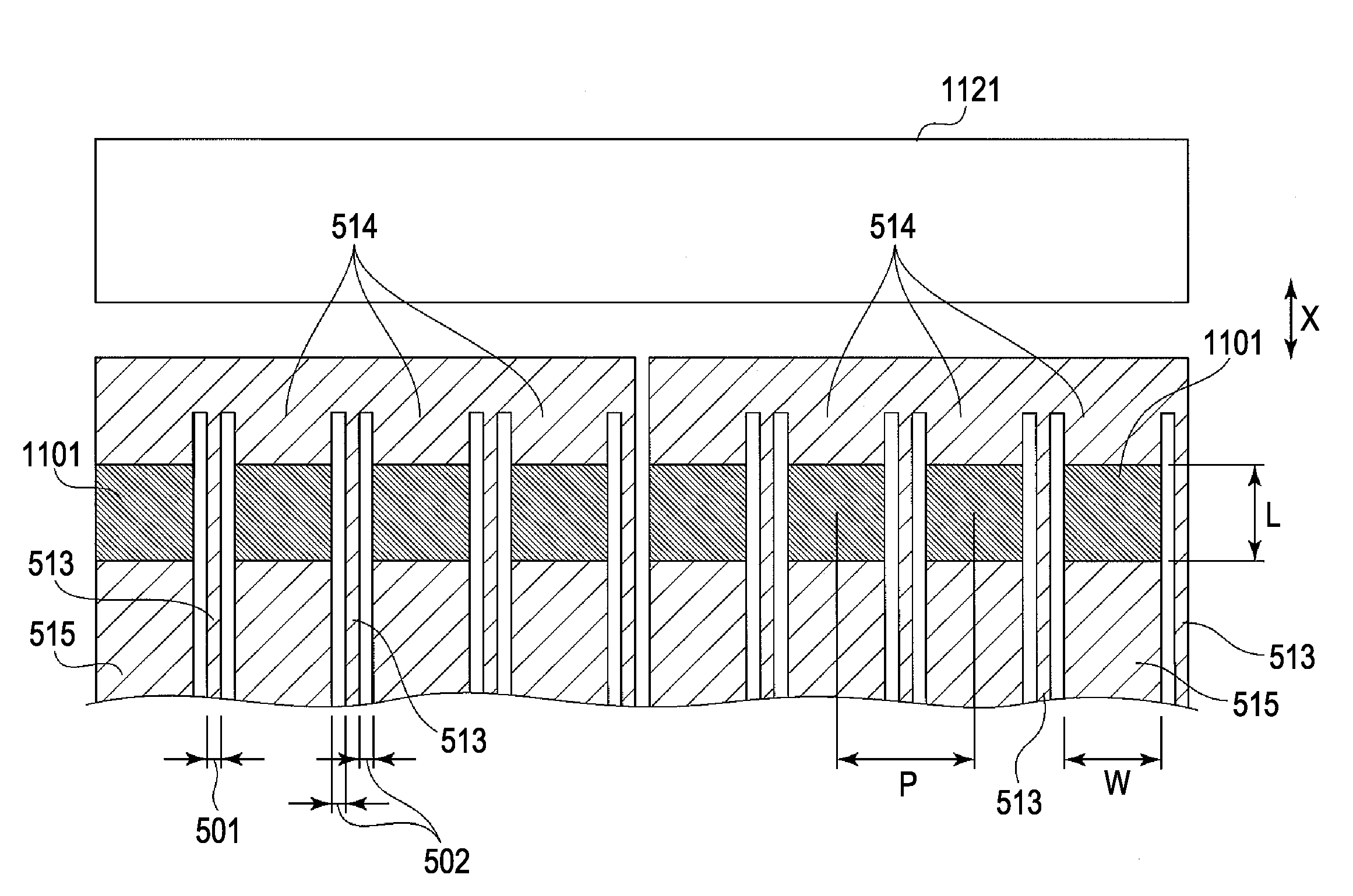
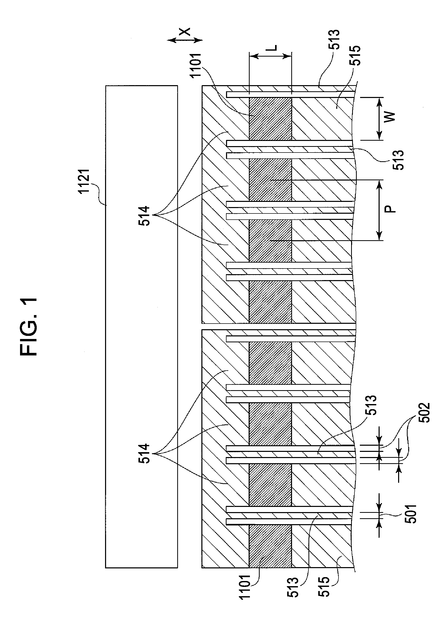
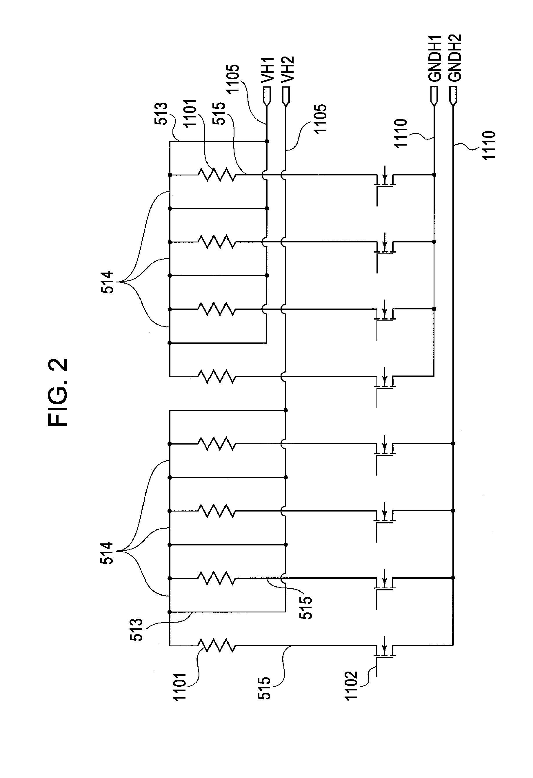
[0033]FIGS. 1 and 2 are explanatory views of a heater portion of a printhead substrate according to a first exemplary embodiment of the present invention.

[0034]Prior to describing the construction of the heater portion of the printhead substrate, which is the feature of the present invention, a description is first given of exemplary constructions of a driving circuit formed in the printhead substrate, signals used to drive the driving circuit, a printhead, and a printing apparatus using the printhead.

Exemplary Construction of Driving Circuit

[0035]The printhead substrate includes, as described in detail later, electrothermal transducers (also called “heaters” hereinafter) and a driving circuit arranged to drive the heaters. The heaters and the driving circuit are formed on the same printhead substrate by employing the semiconductor process technique.

[0036]FIG. 8 is an explanatory circuit diagram illustrating one example of the driving circuit formed on the printhead substrate.

[0037]...

second exemplary embodiment

[0081]FIG. 3 is a schematic plan view illustrating a heater arrangement in a printhead substrate according to a second exemplary embodiment of the present invention, and FIG. 4 is an electric circuit diagram corresponding to the arrangement of heaters 1101 and lines 513, 514 and 515 in FIG. 3. Similar components in FIGS. 3 and 4 to those in the above-described first exemplary embodiment are denoted by the same characters and a description of those components is not repeated here.

[0082]In the second exemplary embodiment of the present invention, as in the first exemplary embodiment, resistances constituting the heaters 1101 are formed in the same layer by using the multilayer wiring technique, and the lines 513, 514 and 515 are also formed in the same layer as the resistances. Further, as in the first exemplary embodiment, the return wirings 513 in each heater group are interconnected by the interconnecting wiring 514, which is formed between a heater array (row) and an ink supply po...


PUM


Abstract

Plural electrothermal transducers (heaters) belonging to each of blocks having different driving timings are constituted as one group and are connected to a common interconnecting wiring in units of one group. Plural lines are connected to the common wiring such that the plural lines are extended to return with respect to the heaters and are each arranged to extend in an adjacent or sandwiched relation to the heaters. A printhead substrate, a printhead, and a printing apparatus can be provided which can realize higher quality of a printed image and a higher printing speed by arraying the heaters at a higher density while ensuring a sufficient area for arrangement of each of the heaters.

Description

BACKGROUND OF THE INVENTION[0001]1. Field of the Invention[0002]The present invention relates to a printhead substrate including electrothermal transducers (heaters) to generate thermal energy for discharging ink. The present invention also relates to a printhead having the printhead substrate assembled therein, and to a printing apparatus configured to print an image by using the printhead.[0003]2. Description of the Related Art[0004]For example, Japanese Patent Laid-Open No. 2002-374163 describes an ink jet printhead in which electrothermal transducers (heaters), a driver, and a logic circuit are formed on a silicon substrate. In accordance with image data, the logic circuit drives the electrothermal transducers through the driver. An arrangement of power supply wirings (lines) for the electrothermal transducers in a substrate (printhead substrate) is described in, e.g., U.S. Pat. No. 6,409,315.[0005]Resolution of a color ink jet printer utilizing the thermal ink jet technique has...

Claims


Application Information

Patent Timeline
Patent Type & Authority Applications(United States)
IPC IPC(8): B41J2/05
CPCB41J2/04541B41J2/14072B41J2/0458B41J2/04543
Inventor TAKEUCHI, SOUTAIMANAKA, YOSHIYUKIOMATA, KOICHIYAMAGUCHI, TAKAAKIKUBO, KOUSUKE
Owner CANON KK
Why Eureka
Try Eureka