Surface emitting laser

Inactive Publication Date: 2008-06-19
ROHM CO LTD
View PDF2 Cites 3 Cited by
  • Summary
  • Abstract
  • Description
  • Claims
  • Application Information

AI Technical Summary

Benefits of technology

[0022]A reflection film whose Al composition ratio is the highest among the Al composition ratios of the respective reflection films in a multilayered reflection film formed in the beam portion connecting the mesa region to the outside region, which is one of the multilayered reflection films constituting the laser resonant

Problems solved by technology

The current blocking layer 25 and the semiconductor layers thereon and thereunder are bonded so weakly that they are likely to suffer from defects such as dislocations and cracks due to thermal stress which is applied thereto in a heating process following the oxidation.
These defects may possibly propagate to the active layer during the operation of the laser, thereby causing non-light emitting area.
The resin surface emitting laser has a problem that the rel

Method used


Image

  • Surface emitting laser
  • Surface emitting laser
  • Surface emitting laser

Examples


Embodiment Construction

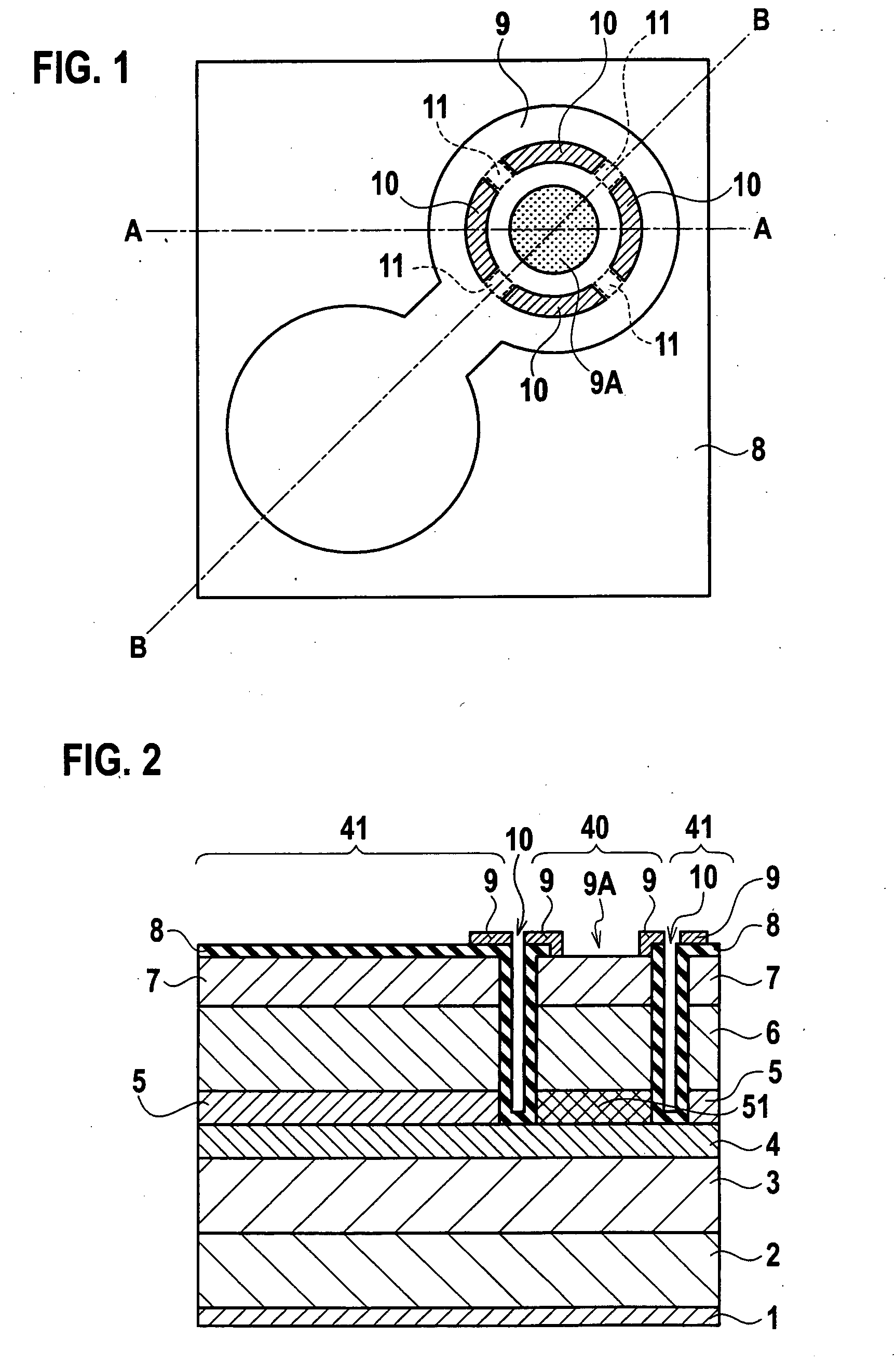
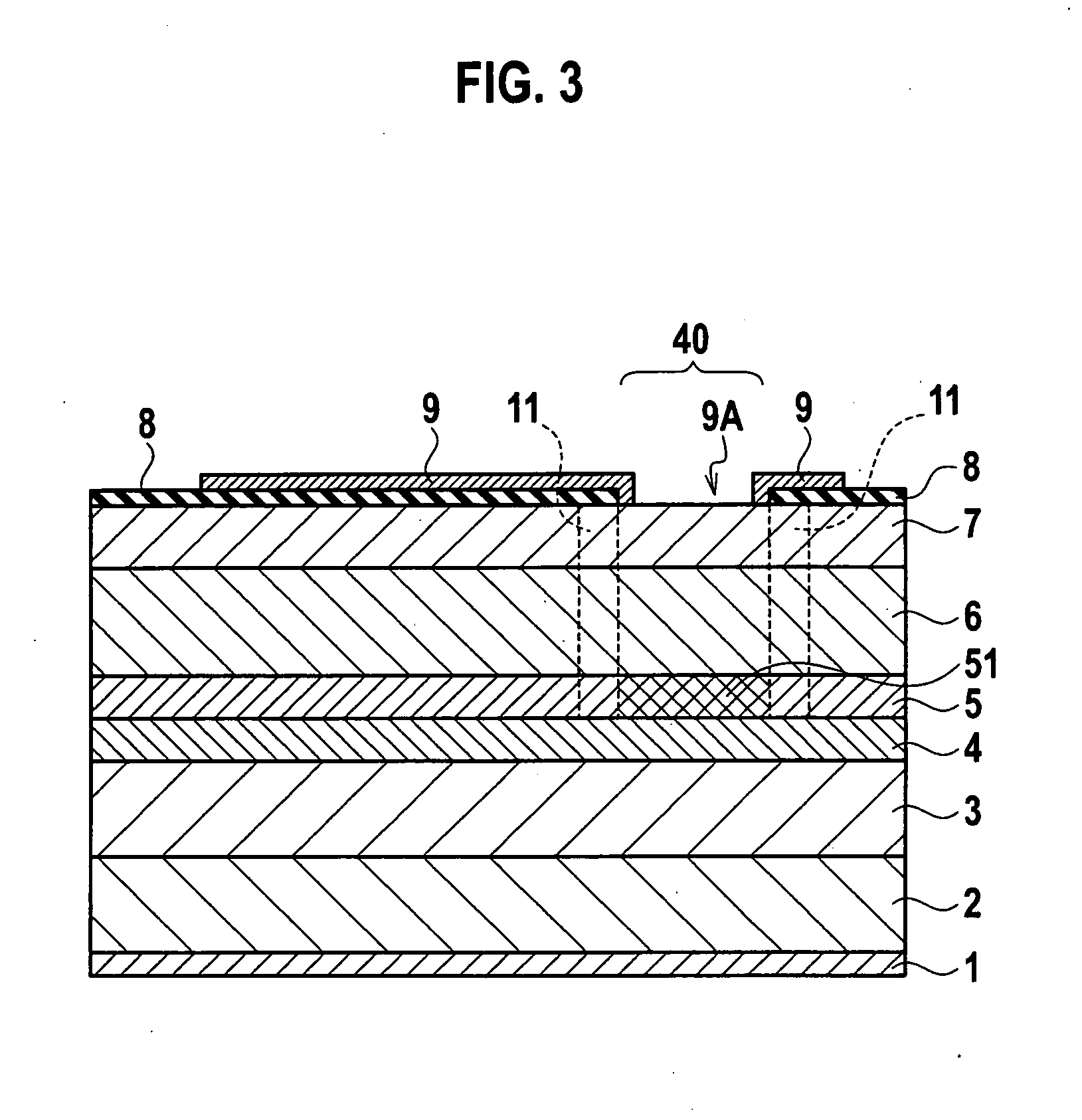
[0029]Descriptions will be provided hereinbelow for an embodiment of the present invention with reference to the drawings. FIG. 1 is a top view of a surface emitting laser according to the present invention, which is viewed from the side through which a laser light beam is emitted. FIG. 2 shows a cross-sectional structure of the surface emitting laser taken along the line A-A of FIG. 1. FIG. 3 shows a cross-sectional structure of the surface emitting laser taken along the line B-B of FIG. 1.

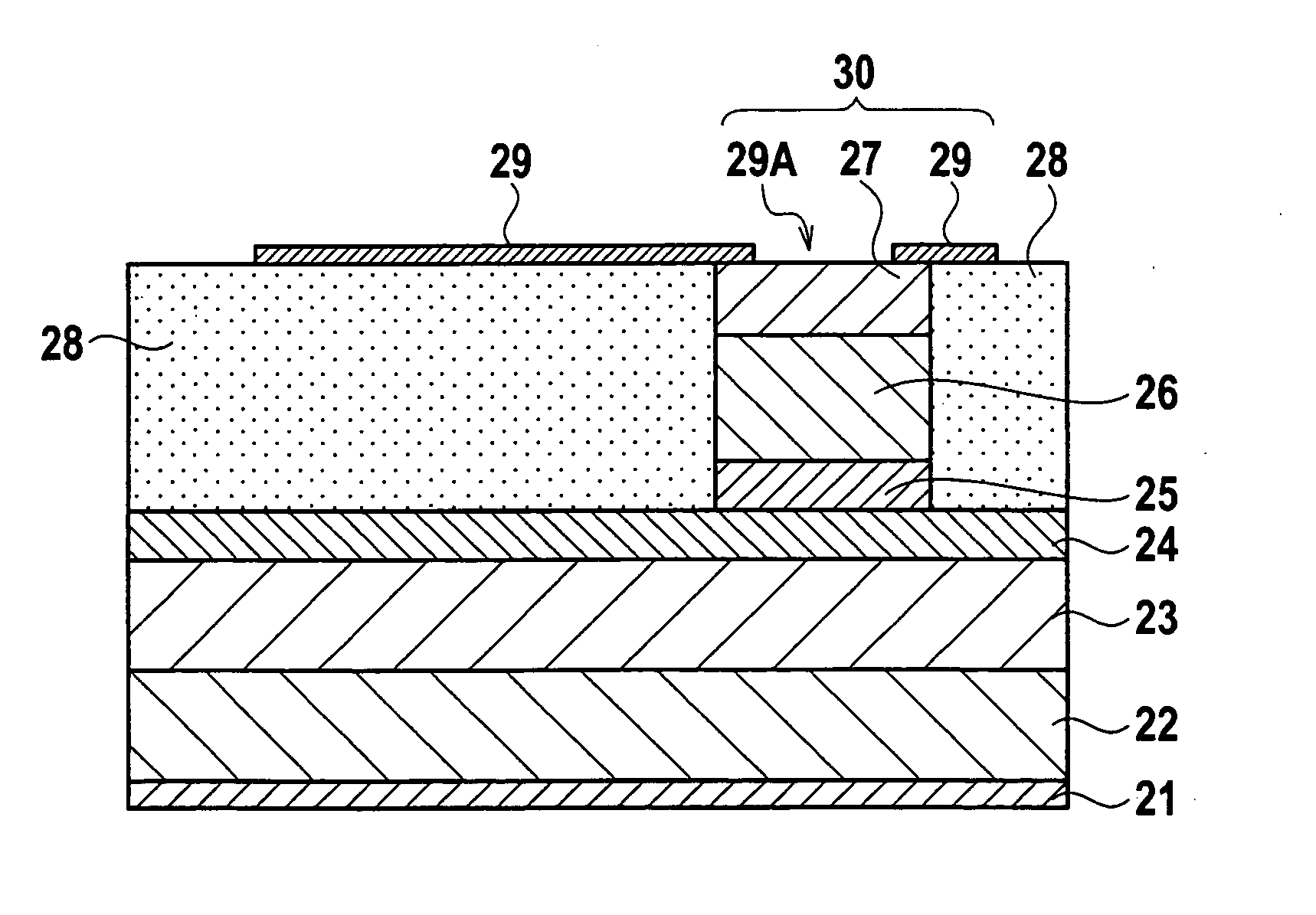
[0030]The surface emitting laser includes an n-side multilayered reflection film 3 and an active layer 4 which are formed on a substrate 2. On the active layer 4, a virtually columnar mesa region 40 is formed by sequentially stacking an Alx3GaAs current blocking layer 51, a p-side multilayered reflection film 6, a p-type contact layer 7 and the like.

[0031]A virtually annular groove 10 separates the mesa region 40 from an outside region 41. The mesa region 40 is surrounded by the outside region 41...


PUM


Abstract

A surface emitting laser includes an n-side multilayered reflection film and an active layer which are formed on a substrate. On the active layer, a mesa region is formed by sequentially stacking an AlGaAs current blocking layer, a p-side multilayered reflection film, a p-type contact layer and the like. A groove is formed to separate the mesa region from an outside region. The mesa region and the outside region are connected to each other with a beam portion provided in the groove. A reflection film with a high Al composition ratio in the p-side multilayered reflection film in the beam portion is completely oxidized, and thus has a high resistance.

Description

CROSS REFERENCE TO RELATED APPLICATIONS AND INCORPORATION BY REFERENCE[0001]This application is based upon and claims the benefit of prior Japanese Patent Application P2006-338178 filed on Dec. 15, 2006; the entire contents of which are incorporated by reference herein.BACKGROUND OF THE INVENTION[0002]1. Field of the Invention[0003]The present invention relates to a vertical-cavity surface-emitting laser, and particularly to a surface emitting laser including a beam portion or bridge beam portion.[0004]2. Description of the Related Art[0005]A surface emitting laser which emits a laser light beam perpendicular to the semiconductor substrate is termed as a vertical-cavity surface-emitting laser (VCSEL). In the surface emitting laser, a p-n junction is formed by stacking GaAs, InGaAs and AlGaAs semiconductor thin films in the vertical direction. Thereafter, on the top and bottom of the p-n junction, two multiplayer reflector mirrors are formed, thus a resonant cavity is obtained. The s...

Claims


Application Information

Patent Timeline
IPC IPC(8): H01S5/183
CPCH01S5/18311H01S2301/176H01S5/18316
Inventor TANAKA, YOSHINORIYAMAMOTO, MASASHI
Owner ROHM CO LTD
Why Eureka
Try Eureka