Intubation instrument

a technology of intubation instrument and endotracheal tube, which is applied in the field of intubation instrument, can solve the problems of blockage of the practitioner's line of sight for inserting such straight devices, inconvenient use, and inconvenient use of the patient's mouth, so as to facilitate rapid and safe placement of the instrument and the associated endotracheal tub

Inactive Publication Date: 2008-06-19
VERATHON
View PDF6 Cites 42 Cited by
  • Summary
  • Abstract
  • Description
  • Claims
  • Application Information

AI Technical Summary

Benefits of technology

[0011]The present invention overcomes these and other problems of known intubation devices. It provides an intubation device that includes...

Problems solved by technology

However, the path from the patient's mouth to the glottis is not straight.
Such manipulation is undesirable, particularly where the patient may have an injured neck or head.
Moreover, the practitioner's line of sight for inserting such straight devices is often blocked by interfering tissue and the like.
However, such a camera view positioned toward the distal end is often unprotected from tissue and debris, and therefore becomes easily blocked.
Moreover, such positioning is usually too close to offer the practitioner a helpful perspective to facilitate proper insertion and alignment of the laryngoscope and endotracheal tube within the larynx.
Also, the straight blade remains difficult to properly insert.
However, to be properly inserted, such devices still require undesirable manipulation of a patient's head and neck.
However, these tips are generally too small to adequately support the epiglottis, and they still require the practitioner to insert an elongate straight or substantially straight blade, thereby required undesirable manipulation of the patent's head and neck.
However, the path from the patient's mouth to the glottis is not straight.
Such manipulation is undesirable, particularly where the patient may have an injured neck or head.
Moreover, the...

Method used


Image

  • Intubation instrument
  • Intubation instrument
  • Intubation instrument

Examples


Embodiment Construction

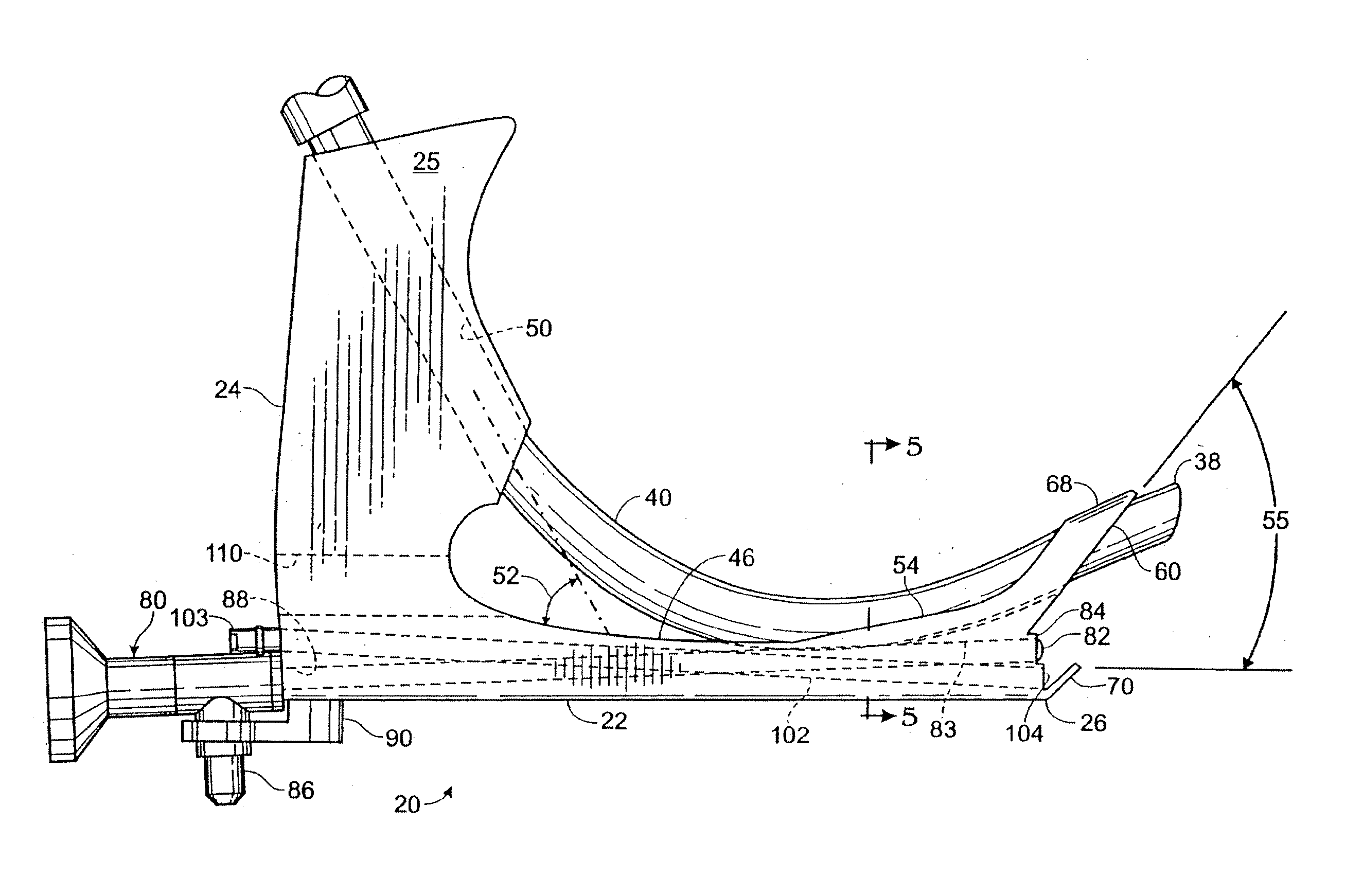
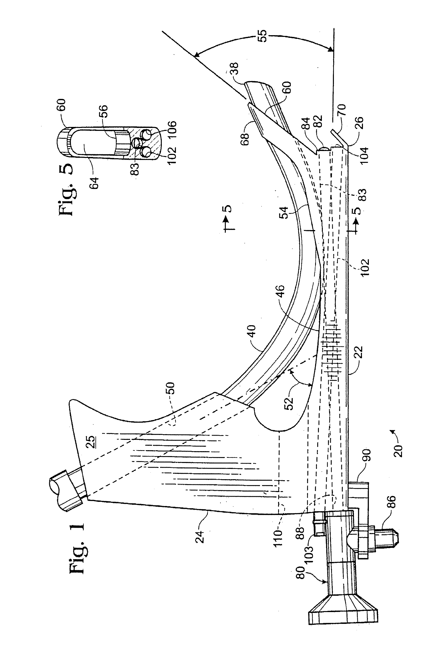
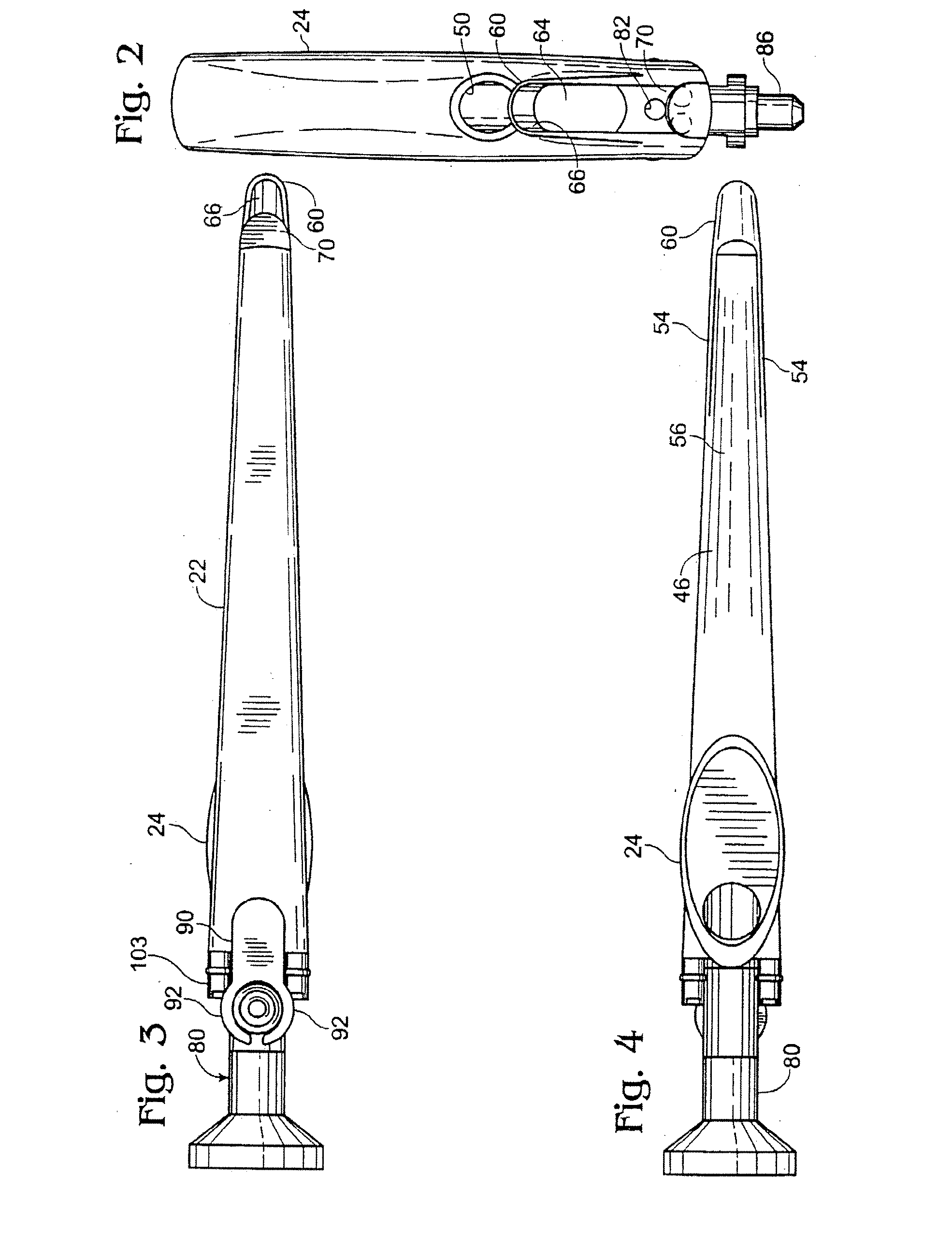
[0067]An improved intubation instrument in accordance with preferred embodiments of the present invention is shown in FIGS. 1-11. In particular, FIGS. 1-6 show a first preferred embodiment, FIGS. 7, 8 and 11A-B show a second preferred embodiment, and FIGS. 9 and 10 show a third preferred embodiment. In order to avoid unnecessary repletion, common elements between these three embodiments are like numbered.

A. First Preferred Embodiment

[0068]With particular reference to FIGS. 1 and 6, a first preferred embodiment of an intubation instrument made and used in accord with the present invention includes a body 20 that generally comprises an elongated arm 22 with integrally attached handle 24. The instrument is preferably formed from metal or rigid plastic that can withstand sterilization.

[0069]The instrument arm has a distal end 26 that is inserted into the mouth 30 of a patient 28. Preferably, the instrument is inserted while the patient is recumbent, face-up, with the head tipped slightl...


PUM


Abstract

The configuration and arrangement of the instrument greatly facilitate safe placement of the instrument and an associated endotracheal tube. The instrument includes a handle with an arm extending therefrom. The arm includes a base portion and a distal lifter portion preferably having an angle between 5° and 85°, inclusive, and the lifter is sized and shaped to engage or lift the patient's epiglottis, thereby to expose the glottis. In a preferred embodiment, the base portion and lifter portion are substantially the same length, and a viewing device, which is preferably a CCD or CMOS camera positioned near the transition portion between the base and lifter portions, is aligned to provide a perspective view toward the distal end of the lifter. Lights, which are preferably LED units, are positioned toward the distal end of the lifter to facilitate viewing. A transparent protective sheathing may be positioned over the assembly to facilitate cleaning and provide sterile multiple use of the device, and the lifter may be pivotally secured to the base portion to facilitate on-site adjustment by the practitioner.

Description

RELATED APPLICATIONS[0001]The following applications are incorporated by reference as if fully set forth herein: U.S. application Ser. Nos. 09 / 732,129 filed Dec. 6, 2000; 10 / 356,705 filed Jan. 30, 2003 and ReExamination Control Number 95 / 000,161.BACKGROUND OF THE INVENTION[0002]Intubation of the human trachea is carried out daily in operating rooms and emergency facilities in order to facilitate respiration of a patient. The goal of the intubation process is to locate the distal end of an endotracheal tube in the larynx with the proximal end outside the patient's mouth.[0003]Safe and effective intubation requires controlled insertion of the endotracheal tube through a patient's mouth so that the tube is directed to the upper part of the larynx, the glottis, without damaging or being blocked by the patient's tissue. To this end, intubation instruments have been developed. Such instruments generally provide a somewhat rigid structure that is inserted into the mouth of the patient so t...

Claims


Application Information

Patent Timeline
IPC IPC(8): A61B1/267A61B1/04G02B23/24A61B1/273A61M16/04G02B23/26
CPCA61B1/042A61B1/05A61B1/2676A61B1/0684A61B1/267A61B1/0676
Inventor PACEY, JOHN A.
Owner VERATHON
Why Eureka
Try Eureka