Prosthesis Deployment Apparatus and Methods

Inactive Publication Date: 2008-06-19
MEDTRONIC VASCULAR INC
View PDF90 Cites 48 Cited by
  • Summary
  • Abstract
  • Description
  • Claims
  • Application Information

AI Technical Summary

Benefits of technology

[0018]According to another embodiment of the invention, a method of real-time imaging a portion of a vessel in a patient comprises securing one or more leadless electromagnetic markers to a vessel of a patient; generating electromagnetic fields about the one or more markers to detect the position of the one or more markers and create a virtual image of a portion of the vessel.
[0019]According to another embodiment of the invention, a method of prosthesis deployment comprises securing a first electromagnetic marker to a vessel of a patient; and tracking the first electromagnetic marker that is secured to the vessel with a second electromagnetic marker secured to a tubular prosthesis while endovascularly advancing the tubular prosthesis toward the first marker; and deploying the prosthesis when the relative position of the first and second markers is in a desired state.
[0020]According to another embodiment of the invention, a method of cannulating a first tubular prosthesis with a second tubular prosthesis in vivo comprises endovascularly positioning a first tubular prosthesis having an open end and an electromagnetic marker adjacent to said open end in a vessel; tracking the first electromagnetic marker that is secured to first the tubula

Problems solved by technology

The abnormally dilated vessel has a wall that typically is weakened and susceptible to rupture.
Although the endovascular approach is much less invasive, and usually requires less recovery time and involves less risk of complication as compared to open surgery, there can be concerns with alignment of asymmetric features of various prostheses in relatively complex applications such as one involving branch vessels.
The procedure becomes more complicated when more than one branch vessel is treated.
One example is when an aortic abdominal aneurysm is to be treated and its proximal neck is diseased or damaged to the extent that it cannot support a reliable connection with a prosthesis.
Not only is there risk of entanglement of these components, the openings in an off the shelf prosthesis with preformed fenestrations may not properly align with the branch vessels due to differences in anatomy from one patient to another.
Prostheses having preformed custom located fenestrations or openings based on a patient's CAT scans also are not free from risk.
A custom designed prosthesis is constructed based on a surgeon's interpretation of the scan and still may not result in the desired anatomical fit.
When the vessel is reshaped, even a custom designed prosthesis may not properly align with the branch vessels.
While physicians always try to use low dose rates during fluoroscopy, the length of a procedure may be such that it results in a relatively high absorbed dose to the patient.
Another challenge with fluoroscopy is that to enable navigation of a catheter to a branch artery such as a renal artery requires registration of where the device is in relation to vascular anatomy.
This is difficult due to the natural movement of vascular anatomy with respiration and cardiac cycles and the change that is imposed on the vessel when catheters and wires are introduced.

Method used


Image

  • Prosthesis Deployment Apparatus and Methods
  • Prosthesis Deployment Apparatus and Methods
  • Prosthesis Deployment Apparatus and Methods

Examples


Embodiment Construction

[0043]The following description will be made with reference to the drawings where when referring to the various figures, it should be understood that like numerals or characters indicate like elements.

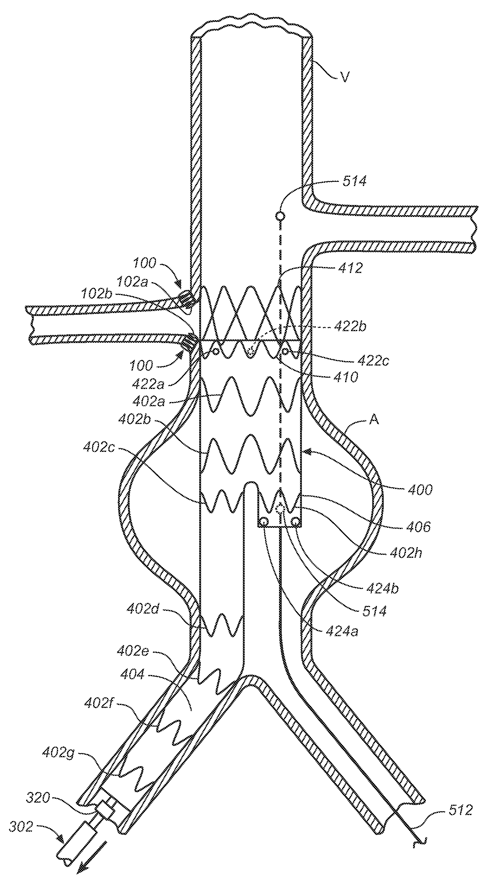
[0044]Regarding proximal and distal positions, the proximal end of the prosthesis (e.g., stent-graft) is the end closest to the heart (by way of blood flow) whereas the distal end is the end farthest away from the heart during deployment. In contrast, the distal end of the catheter is usually identified as the end that is farthest from the operator, while the proximal end of the catheter is the end nearest the operator. Therefore, the prosthesis (e.g., stent-graft) and delivery system proximal and distal descriptions may be consistent or opposite to one another depending on prosthesis (e.g., stent-graft) location in relation to the catheter delivery path.

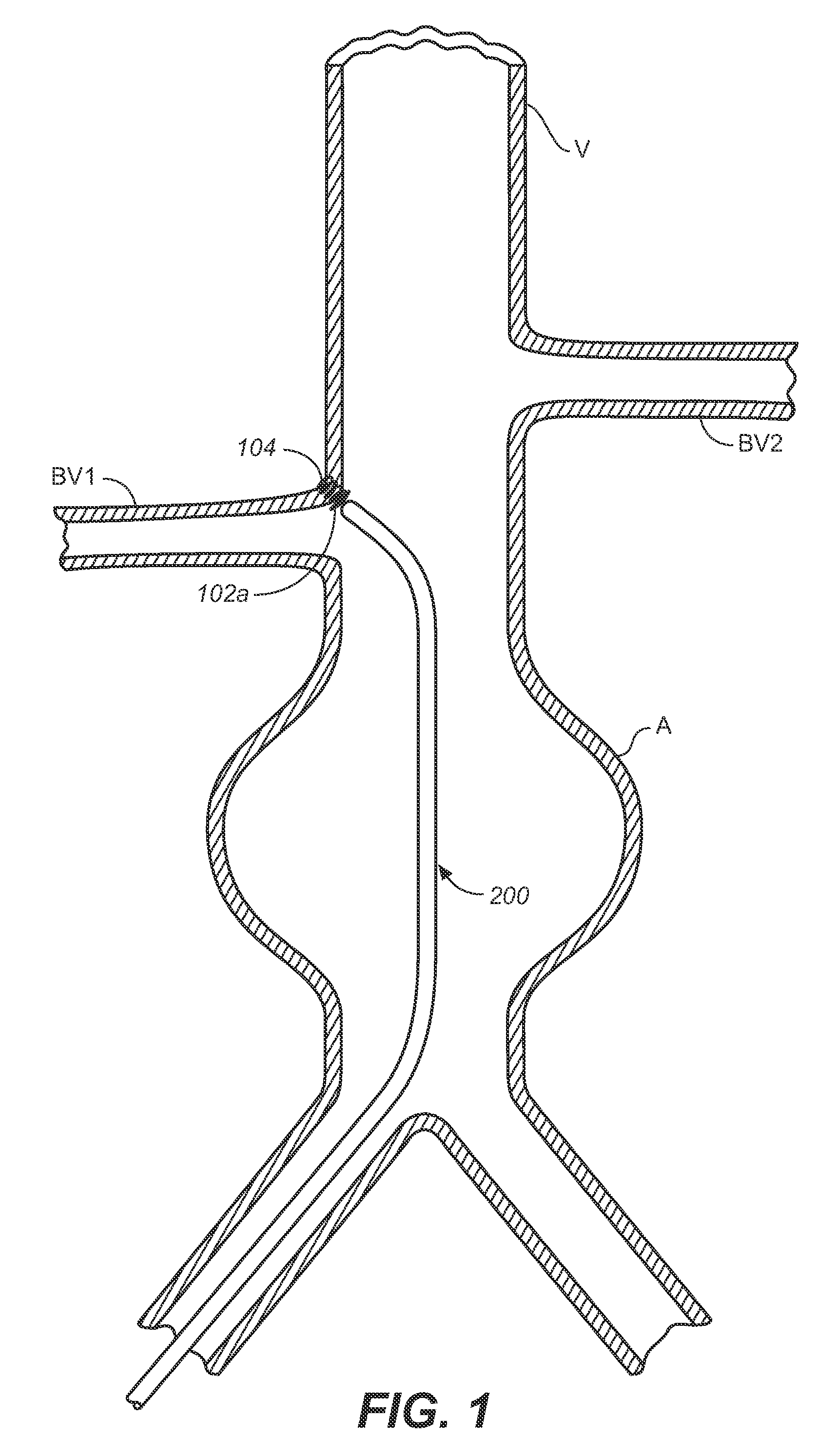
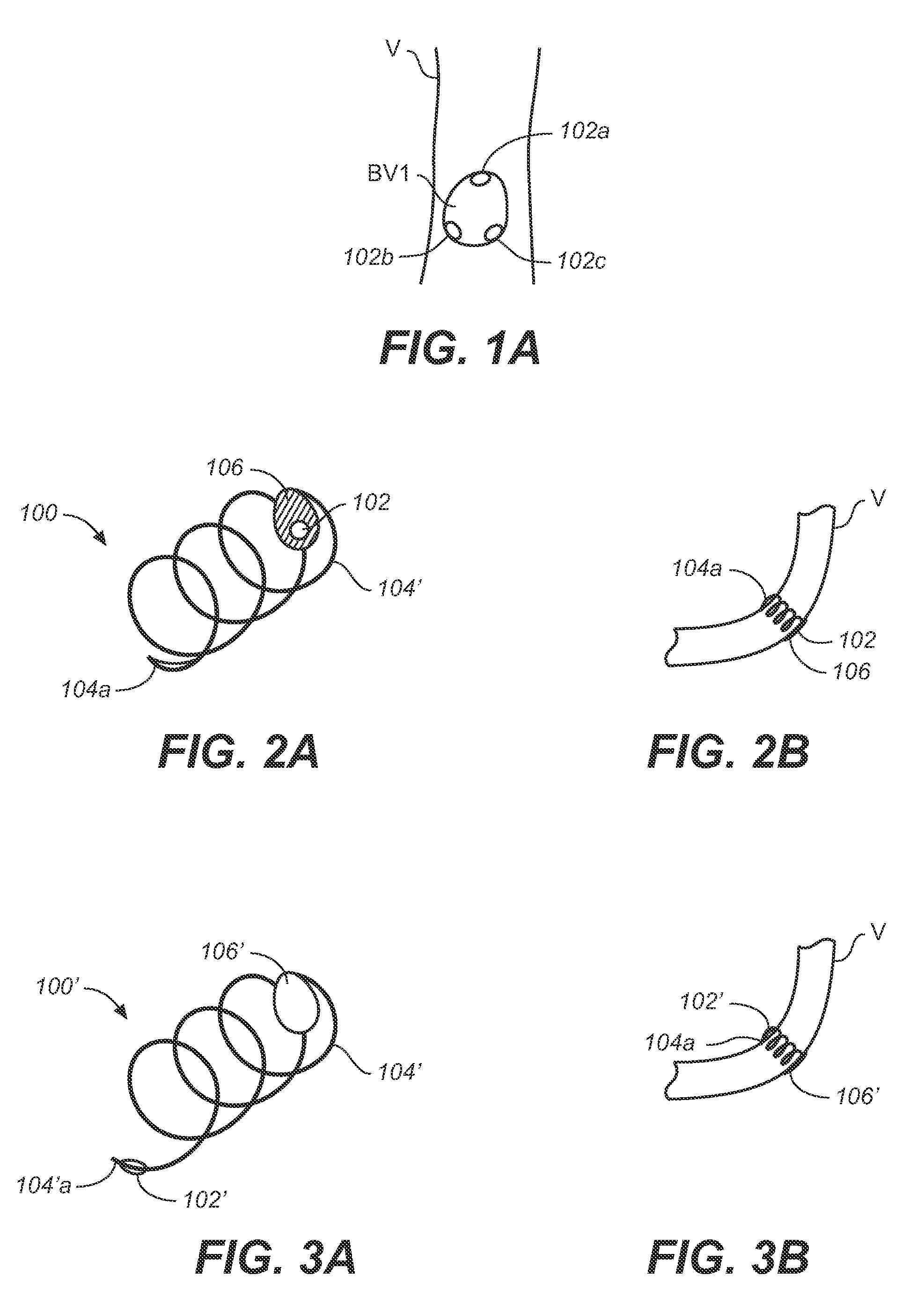
[0045]According to one embodiment of the invention, one or more localization markers are implanted at a target site in a patient's ve...


PUM


Abstract

One or more localization markers are implanted in a patient's vessel to provide a virtual image of a portion of the vessel, provide a target for deploying a prosthesis, and / or facilitate post operative surveillance of a deployed prosthesis (e.g., to measure prosthesis migration and / or aneurysm elongation). In the case of providing a target or facilitating surveillance, one or more localization markers also can be provided on the prosthesis (e.g., the proximal end portion of the prosthesis) and the position of the prosthesis marker(s) monitored relative to the implanted marker(s). In another embodiment, one or more localization markers are provided adjacent to one opening of a tubular prosthesis to assist with cannulation of the opening. In one example, one or more localization markers are provided on the contralateral stump of a modular bifurcated stent-graft (e.g., to assist a surgeon with inserting a contralateral stent-graft into the contralateral stump of a modular bifurcated stent-graft). One or more localization markers can be provided on a guidewire and tracked to the one or more localization markers on the contralateral stump and the contralateral stent-graft tracked thereover.

Description

FIELD OF THE INVENTION[0001]The invention relates to prosthesis deployment in the human vascular system and / or post deployment management.BACKGROUND OF THE INVENTION[0002]Tubular prostheses such as stents, grafts, and stent-grafts (e.g., stents having an inner and / or outer covering comprising graft material and which may be referred to as covered stents) have been widely used in treating abnormalities in passageways in the human body. In vascular applications, these devices often are used to replace or bypass occluded, diseased or damaged blood vessels such as stenotic or aneurysmal vessels. For example, it is well known to use stent-grafts, which comprise biocompatible graft material (e.g., Dacron® or expanded polytetrafluoroethylene (ePTFE)) supported by a framework (e.g., one or more stent or stent-like structures), to treat or isolate aneurysms. The framework provides mechanical support and the graft material or liner provides a blood barrier. The graft material for any of the p...

Claims


Application Information

Patent Timeline
IPC IPC(8): A61F2/06
CPCA61B17/068A61F2002/9534A61B19/54A61B2017/0649A61B2019/505A61B2019/5251A61B2019/5289A61B2019/5408A61B2019/5454A61B2019/5483A61B2019/5487A61F2/07A61F2002/067A61F2250/0096A61F2/89A61B19/5244A61B2090/3983A61B34/20A61B2090/364A61B2034/105A61B2034/2051A61B90/39A61B2090/3908A61B2090/3954A61B2090/3987
Inventor MCIFF, GREGYAMASAKI, DWAYNE S.SIMON, DAVIDGARDESKI, KENNETH
Owner MEDTRONIC VASCULAR INC
Why Eureka
Try Eureka