Mri Imaging of an Object in Cyclic Motion

a cyclic motion, magnetic resonance imaging technology, applied in the direction of magnetic measurement, geological measurement, reradiation, etc., can solve the problems of loss of scan efficiency, only available images, and the optimal time may still be quite long, so as to improve the scan efficiency

Inactive Publication Date: 2008-06-26
ROYAL BROMPTON & HAREFIELD NHS TRUST
View PDF10 Cites 0 Cited by
  • Summary
  • Abstract
  • Description
  • Claims
  • Application Information

AI Technical Summary

Benefits of technology

[0007]The invention provides improved scan efficiency using Multip

Problems solved by technology

This problem is particularly acute when imaging structures within the thorax of a subject, as they are subject to cyclic motion from the subject's breathing during a typical timescale for image acquisition.
The problem has been addressed by the use of so-called ‘navigator acceptance’ imaging methods in which positional information is gathered effectively simultaneously with image data, but these have been hinde

Method used


Image

  • Mri Imaging of an Object in Cyclic Motion
  • Mri Imaging of an Object in Cyclic Motion
  • Mri Imaging of an Object in Cyclic Motion

Examples


embodiment 1

‘Spaced Part’ Acquisition Order

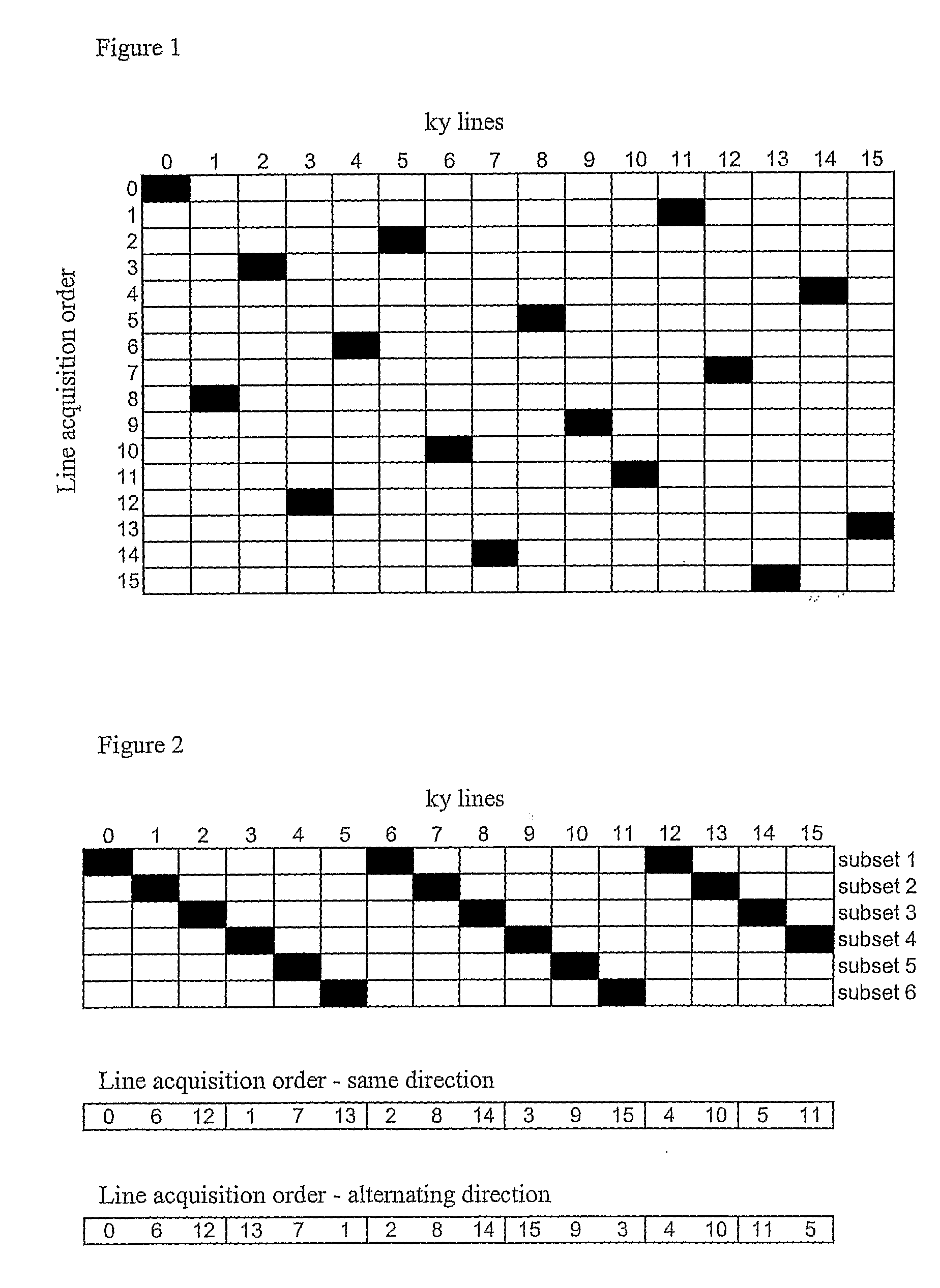
[0047]FIG. 1 illustrates a scheme for a ky line acquisition where the order of lines is spaced apart across the ky space. For illustrative purposes only, a situation where 16 ky lines are to be acquired is illustrated. Each column in the grid represents one line, and the black squares represent the order in which the lines are to be acquired, each acquisition step being represented by a row in the grid. Thus, in this example, the predetermined order for ky line acquisition is as follows:

0115214841219610315713

i.e. the left-most ky line (line 0) is collected first, followed by line 11, line 5 etc., and finally collecting line 13.

[0048]It can be seen that, in this illustration, each subsequent ky line to be acquired is spaced apart across the entire ky space to ensure that, as the data are collected, signal collection is carried out for all frequency bands, rather than being concentrated merely at one end of ky space.

embodiment 2

Interleaved Acquisition Order (N=6)

[0049]FIG. 2 illustrates a scheme for determining a ky acquisition order comprised of subsets of lines to be acquired, with each subset comprising lines equally spaced across the ky space; in this instance, each subset contains every sixth line in the ky space, from one side to the other. It can be seen that each subsequent subset is interleaved with the preceding one thus covering the entire ky space with 6 subsets. Thus, if the acquisition direction is the same for each subset, the acquisition order will be:

subset 1subset 2subset 3subset 4subset 5subset 60612171328143915410511

and if the acquisition order of each successive subset is reversed, then the order will be:

subset 1subset 2subset 3subset 4subset 5subset 60612137128141593410115

embodiment 3

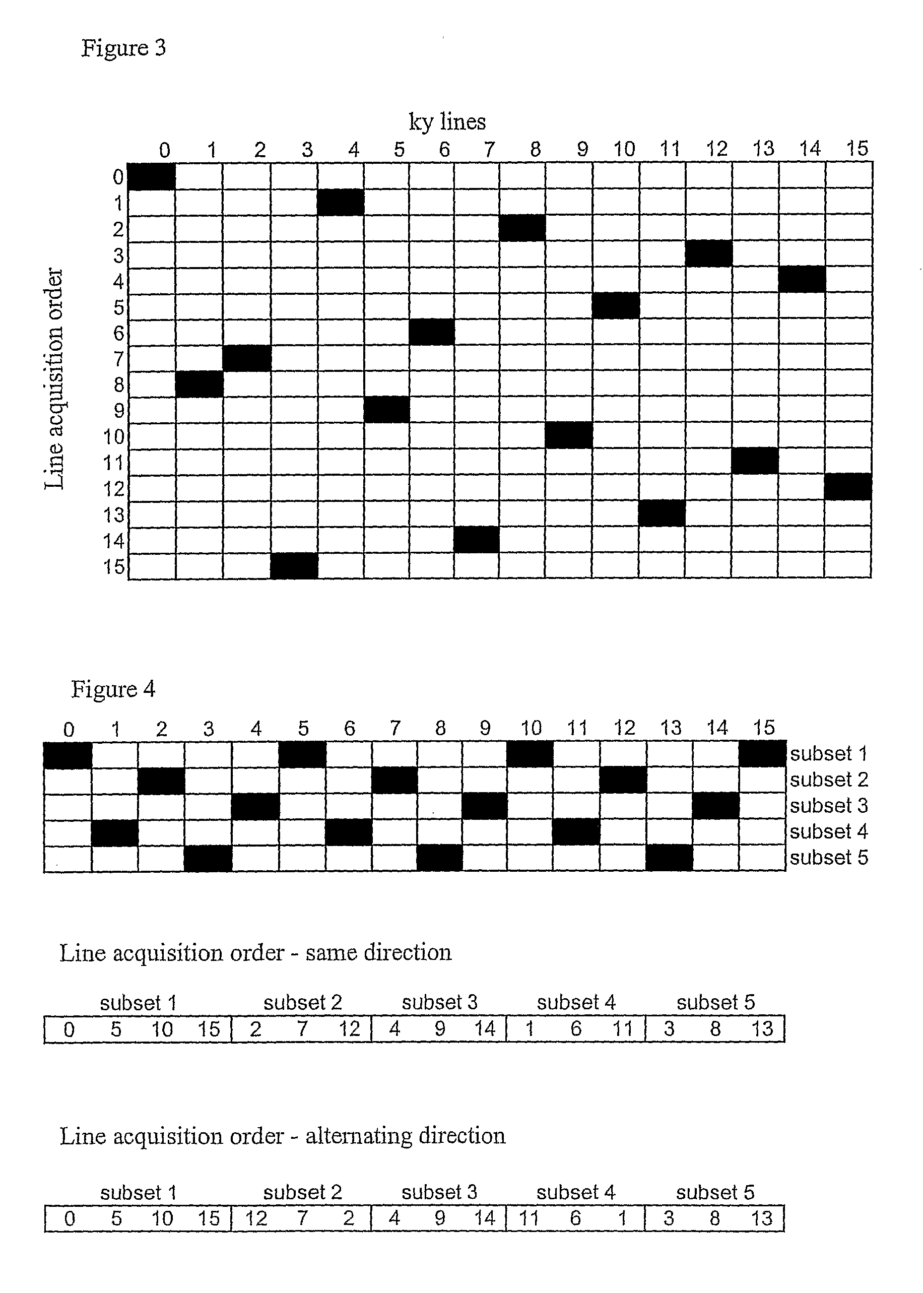
[0050]FIG. 3 illustrates a line acquisition scheme, again illustrated for an image acquisition comprising 16 ky lines. In this case, each subset of lines is spaced apart across the ky space by selecting each fourth line per subset. Each successive subset is then chosen such that it is spaced, and preferably centred, between those ky lines already acquired, so as to ‘fill in the gaps’ evenly across ky space. In this embodiment, successive subsets of ky line acquisition traverse the ky space in alternating directions. The ky line acquisition order is thus:

subset 1subset 2subset 3subset 40481214106215913151173


PUM


Abstract

A method of generating an MRI image of an object in cyclic motion by acquiring ky line data in a spaced apart fashion over ky space using a predefined order for line acquisition for each of a number of position bands. The acquisition orders for adjacent bands are circularly shifted with respect to each other.

Description

FIELD OF THE INVENTION[0001]The invention relates to image acquisition for magnetic resonance imaging (MRI), and in particular to a motion-resistant technique for image capture.BACKGROUND AND PRIOR ART KNOWN TO THE APPLICANT[0002]Magnetic resonance imaging has become established as a key technique for imaging the soft tissues of the body. MRI images are predominantly formed by the measurement of radio frequency signal emission during proton spin relaxation following an excitation signal to protons located in a magnetic field. The use of magnetic field gradients allows spatially encoded data to be acquired to form an image. The data are acquired in so-called “k-space”, related via Fourier transform to the physical space from where an image is acquired—different positions in “k space” correspond to spatial frequency and phase information. The task of forming an MRI image can be viewed as acquiring lines in k-space (“ky lines”) to span the entire k-space to be imaged, and then reconstr...

Claims


Application Information

Patent Timeline
IPC IPC(8): G01R33/483G01R33/567
CPCG01R33/5676G01R33/5673
Inventor JHOOTI, PERMJIT
Owner ROYAL BROMPTON & HAREFIELD NHS TRUST
Why Eureka
Try Eureka