Wavelength control method controlling waveform for recording or reproducing information with holography, hologram information processing apparatus and hologram recording medium

a control method and waveform technology, applied in the field of information processing apparatus and information recording medium, can solve the problems of variable wave length, affecting interference phenomena, and sn ratios extremely poor, and achieve the effect of reducing adjustment tim

Inactive Publication Date: 2008-06-26
SHARP KK
View PDF10 Cites 5 Cited by
  • Summary
  • Abstract
  • Description
  • Claims
  • Application Information

AI Technical Summary

Benefits of technology

[0045]The invention has been made for overcoming the above problems, and an object of the invention is to provide a wavelength control method, a hologram information processing apparatus and a hologram recording medium that allows reading of a wavelength control pattern that is a special patter even when a large deviation is present between a wavelength in an information recording operation and a wavelength in a reproducing operation, allows easy setting of a reproduction wavelength and a record wavelength, and can reduce an adjustment time.

Problems solved by technology

In these operations, variations in wave length are liable to affect the interference phenomenon.
If the wave lengths of the object light and the reference light in the reproducing operation are different from those in the recording operation, a wave surface with respect to the hologram recording medium in the recording operation is different from that in the reproducing operation, resulting in a problem that the SN ratio is extremely poor.
However, when the hologram recording medium expands or shrinks due to changes in temperature as compared with the density in the record processing, this results in a problem that the optimum reproduction wavelength is different from the wavelength in the record processing.
However, the special pattern cannot be detected when a large deviation is present between the record wavelength and the reproduction wavelength in the prior art.
Also, a long time is required for the detection.
Further, correct adjustment may be impossible if the tilting, tracking and focus control are performed when the wavelength has not been adjusted sufficiently.

Method used


Image

  • Wavelength control method controlling waveform for recording or reproducing information with holography, hologram information processing apparatus and hologram recording medium
  • Wavelength control method controlling waveform for recording or reproducing information with holography, hologram information processing apparatus and hologram recording medium
  • Wavelength control method controlling waveform for recording or reproducing information with holography, hologram information processing apparatus and hologram recording medium

Examples


first embodiment

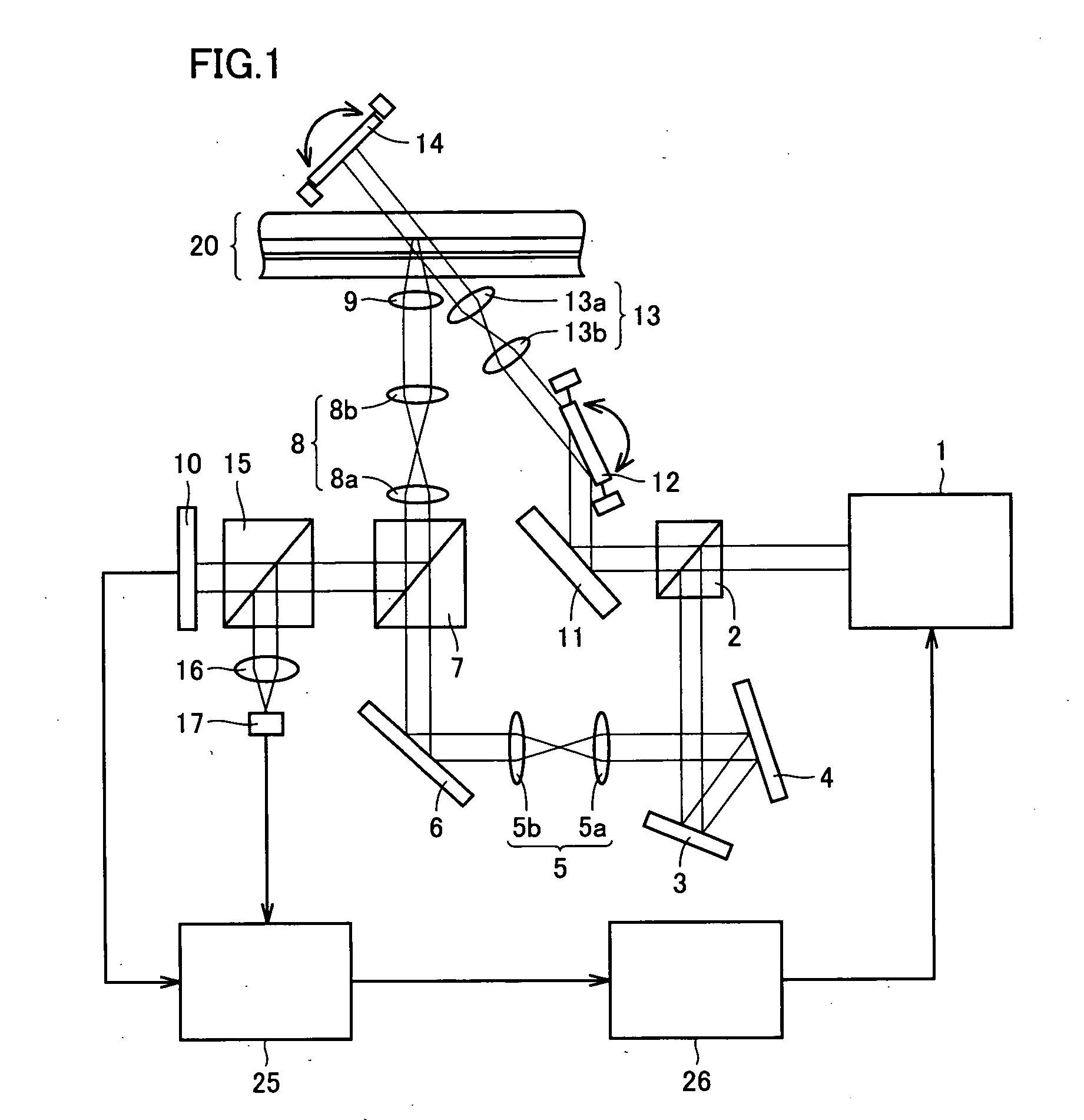
[0091]Referring to FIG. 1, a-schematic structure of a hologram information processing apparatus according to a first embodiment of the invention will be described below.

[0092]Referring to FIG. 1, the hologram information processing apparatus according to the first embodiment of the invention includes a wavelength-variable laser light source 1 for record and reproduction, a first beam splitter 2, a first reflection mirror 3, a spatial light modulator 4, first relay lenses 5 (5a and 5b), a second reflection mirror 6, a second beam splitter 7, second relay lenses 8 (8a and 8b), an objective lens 9, an image-taking element 10, a third reflection mirror 11, a first galvanomirror 12, a lens system 13 (13a and 13b), a second galvanomirror 14, a third beam splitter 15, a lens 16, a light receiving element 17, a signal processing circuit 25 and a wavelength adjustment control unit 26.

[0093]Light emitted from wavelength-variable laser light source 1 is reflected by first beam splitter 2 and f...

second embodiment

[0179]Referring to FIG. 10, description will now be given on a hologram recording medium according to a second embodiment of the invention.

[0180]Referring to FIG. 10, a hologram recording medium 21 according to the second embodiment of the invention differs from hologram recording medium 20 in FIG. 3 in that a wavelength control pattern 82 is employed instead of wavelength control patterns 80 and 81.

[0181]In this example, the wavelength control pattern is recorded at the same location with a plurality of wavelengths (wavelength multiplexing).

[0182]The first embodiment has already been described in connection with the case in which the wavelength control pattern is recorded with the plurality of wavelengths while changing the record light quantity according to a certain rule. In the first embodiment, all the minute mirrors in the spatial light modulator are set uniformly so that the information that is distinguishable from the other is not born. Thus, all the special data items (i.e....


PUM


Abstract

For controlling a wavelength of laser light of a wavelength-variable laser (step S0), an optical system or a hologram recording medium is moved (step S1) to attain a state in which a light beam enters a wavelength control pattern. Reference light that is the laser light is applied to the wavelength control pattern (step S2). Then, a light receiving element observes reproduction light from the wavelength control pattern (step S3). A wavelength of the reference light that is the laser light is minutely changed. A quantity of the reproduction light changes with the wavelength. The quantity of the reproduction light is monitored to obtain a specific wavelength λ0 (a rotation angle of a diffraction grating 52) maximizing the quantity of the reproduction light (step S4). The wavelength of the laser light of the wavelength-variable laser light source is adjusted (step S5).

Description

[0001]This nonprovisional application is based on Japanese Patent Application No. 2006-338731 filed with the Japan Patent Office on Dec. 15, 2006, the entire contents of which are hereby incorporated by reference.BACKGROUND OF THE INVENTION[0002]1. Field of the Invention[0003]The present invention relates to an information processing apparatus and an information recording medium, and particularly to a hologram information processing apparatus and a hologram recording medium for recording and / or reproducing information with holography.[0004]2. Description of the Background Art[0005]Holography recording that records information on hologram recording medium with holography in the prior art is generally performed in such a manner that object light containing image information and reference light for recording are superimposed on each other in the hologram recording medium, and an interference pattern produced thereby is written into the hologram recording medium.[0006]For reproducing th...

Claims


Application Information

Patent Timeline
Patent Type & Authority Applications(United States)
IPC IPC(8): G03H1/02
CPCG03H1/22G03H1/2286G03H2001/2289G11B7/126G11B7/0065G11B7/00736G11B7/00772G03H2222/10
Inventor KANAZAWA, YASUNORIUEYAMA, TETSUO
Owner SHARP KK
Why Eureka
Try Eureka