
Water treatment pad for core drill

a technology for treating pads and core drills, applied in the direction of manufacturing tools, borehole/well accessories, transportation and packaging, etc., can solve the problems of difficult removal, easy clogging of the water treatment pad, and not always providing a significant effect, so as to reduce the pressure space, and improve the effect of drainag

Inactive Publication Date: 2008-07-03
SHIBUYA CO LTD
View PDF7 Cites 3 Cited by
  • Summary
  • Abstract
  • Description
  • Claims
  • Application Information

AI Technical Summary

Benefits of technology

[0011]The present invention is a water treatment pad for core drill which has been made based on the above-described background, and its principal purpose is to provide high drainage efficiency irrespective of postures of drilling work.
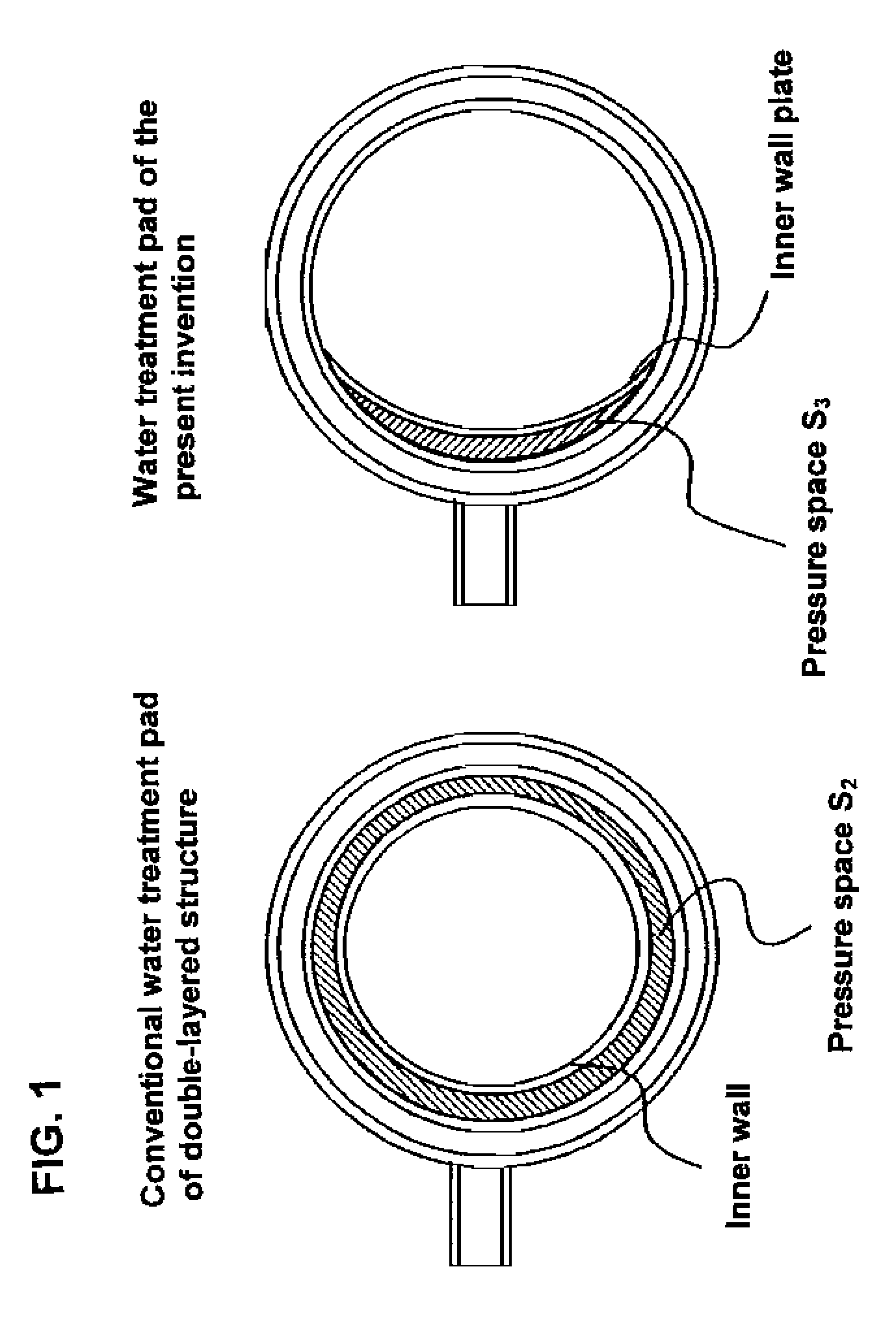
[0025]As described above, the present invention provides efficient discharge of cutting water irrespective of any work posture. The present invention is configured so that an inner wall plate is detachable, thereby attaining easy inside cleaning after work and high maintainability.

Problems solved by technology

However, even the water treatment pad of a double-layered structure does not always provide a significant effect.
To reduce the cross section (S2) of the pressure space, it is necessary to reduce a clearance between an inner surface and an inner wall of the pad main body, however, reducing the clearance causes concrete fragments, cutting chips or the like generated during drilling work to be easily clogged therein, which makes it difficult to remove them.
Failure of the removal would cause them to be stuck by drying, thus making the pad itself unusable.
Accordingly, as a water treatment pad, a water treatment pad with a somewhat larger clearance has been used in consideration of maintainability, however, it has a problem of inferior drainage efficiency, resulting in water residue often occurring in the pad.
After drilling work, removing a pad with a large amount of residue water left causes the residue water to pollute a working position.
In addition to the above-described problem with drainage efficiency during suction, conventional water treatment pads have a problem of difficult drainage depending upon a work posture.
In the case of such a layout, however, with a contact of an outlet of the drain opening with a floor surface or the curvature of a hose connected to the drain outlet taken into consideration, drilling under a wall surface will become difficult.
This problem remarkably occurs especially when the drain opening is directed upward from the horizon, and cutting water continues to gather with little discharge and eventually flows out from an opening in the top of the pad (core drill insertion hole).
Such a problem cannot be solved even by adopting a pad of a double-layered structure and a cleaner.
This is because a conventional pad of a double-layered structure cannot reduce a pressure space as described above, and cannot provide a sufficient suction force of the cleaner.

Method used


Image

  • Water treatment pad for core drill
  • Water treatment pad for core drill
  • Water treatment pad for core drill

Examples


first embodiment (

Drilling Floor Surface)

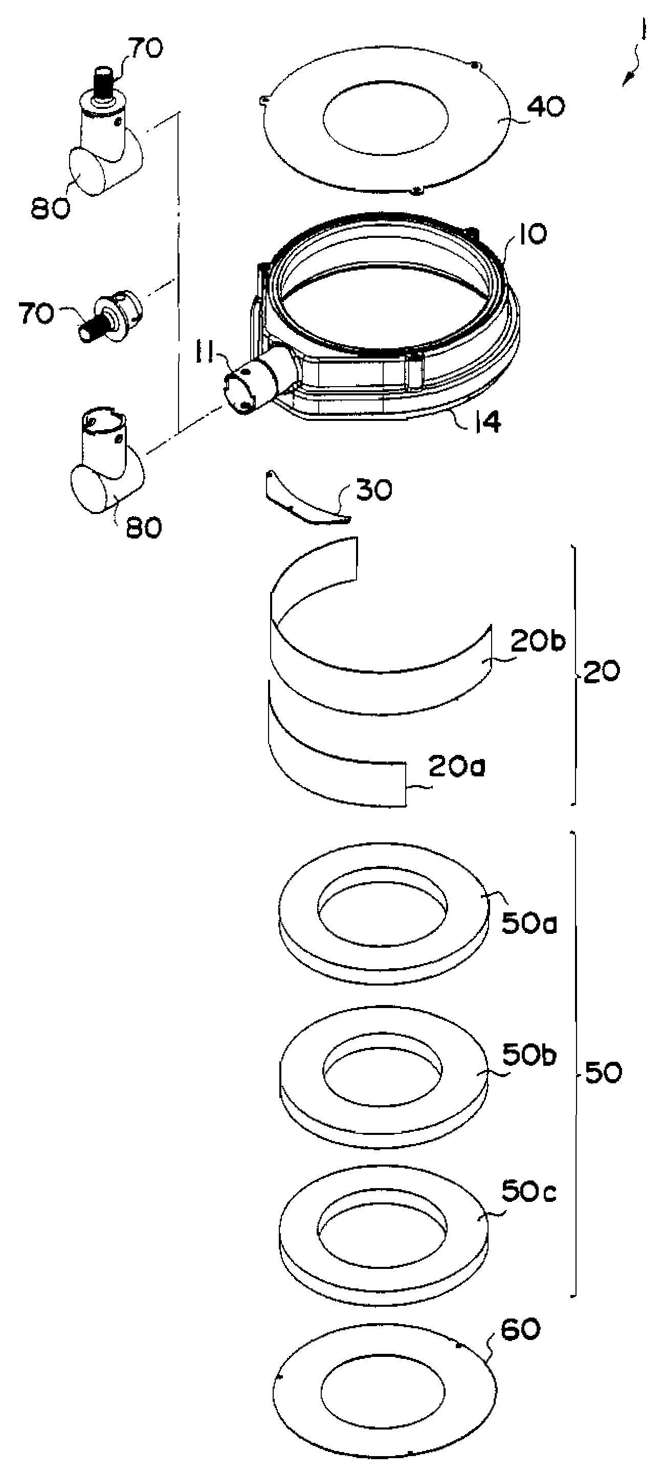
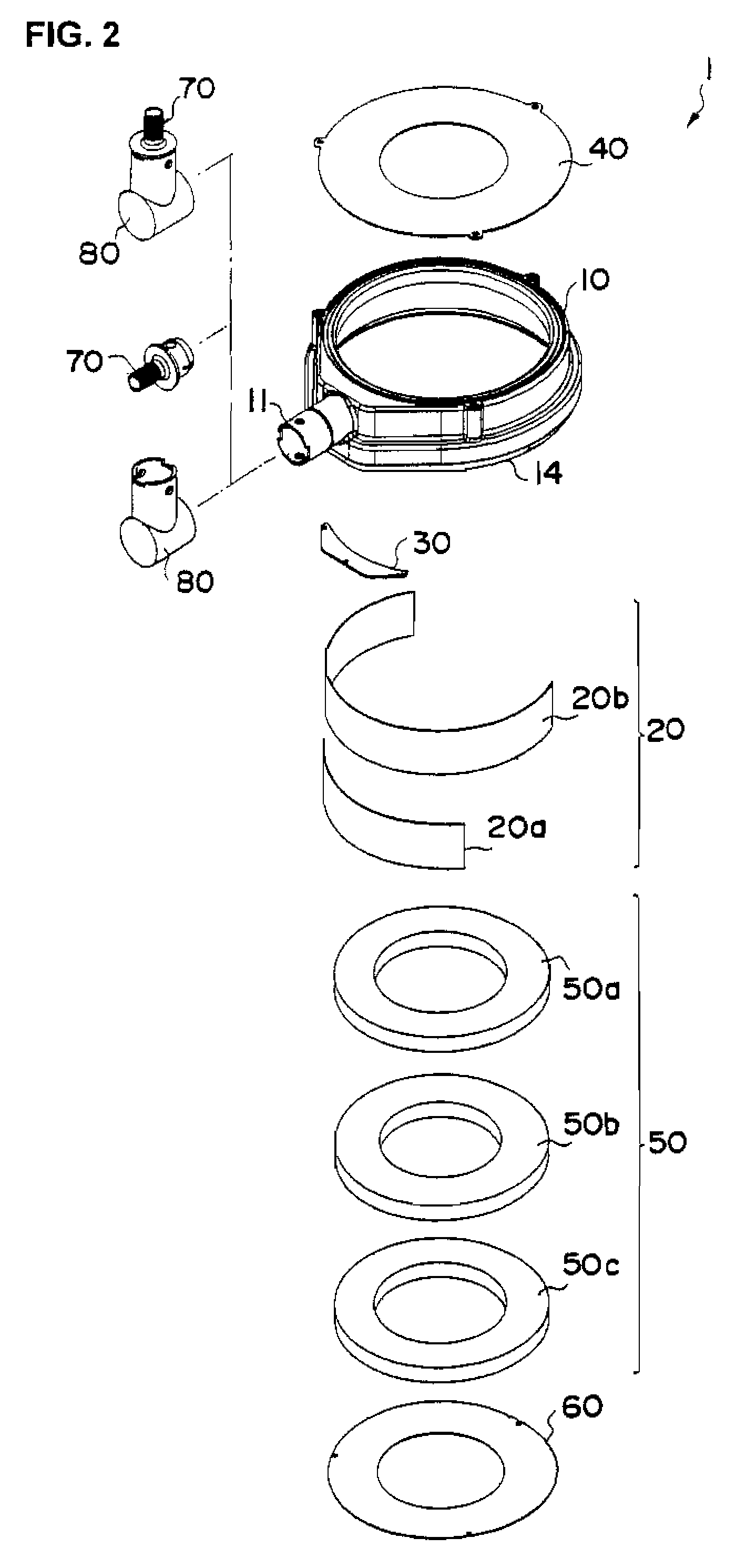
[0047]To drill a floor surface with the water treatment pad 1 according to the present embodiment, the water treatment pad 1 is composed of the pad main body 10 and the inner wall plate 20a. The shielding plate 30 may be included in the water treatment pad 1. In drilling work, as shown in FIG. 5, the water treatment pad is attached onto a floor surface and a vacuum cleaner (not shown) is connected to the drain outlet 11. In installation, the pad 1 is fixed from the above, by which the sponge rubber 14 at the lower end of the pad main body 10 contracts to keep a static suction head by the cleaner low. After attachment and fixing of the water treatment pad 1, a core drill C is located at a drilling position from a top opening and a drive motor (not shown) is actuated to start drilling. During drilling work, cutting water is supplied from the inside of the core drill C and the cutting water rises to a position of a cutting water line L, however, is sucked by the ...

second embodiment (

Drilling Wall Surface)

[0050]To drill a wall surface with the water treatment pad 1 according to the present embodiment, the water treatment pad 1 is composed of the pad main body 10, the inner wall plate 20b and the shielding plate 30. FIG. 7 shows a perspective rear view of a state where these members are combined. The shielding plate 30 in the present embodiment is a roughly trapezoidal plate member adapted to a shape of around the drain outlet 11. Attaching the shielding plate 30 permits a space formed by a bump portion near the drain outlet 11 to be thrust out of the pressure space, thus reducing the volume (cross section) of the pressure space.

[0051]The inner wall plate 20b used in drilling a wall surface is longer than the inner wall plate 20a. This is because the position of the pressure space should be adjusted in accordance with the attachment state of the pad 1. In other words, as described below, drilling a wall surface needs adjusting orientation of the drain outlet in c...

third embodiment (

Drilling Ceiling Surface)

[0055]The water treatment pad according to the present embodiment is applicable to drilling a ceiling surface. In this case, the water treatment pad 1 is constituted of the pad main body 10 and the lower circular plate 60. In drilling a ceiling surface, the inner wall plates 20a, 20b and the shielding plate 30 do not have to be used, but may be provided.

[0056]FIG. 9 is a sectional view of the water treatment pad 1. The lower circular plate 60 has a hole for inserting a core drill in the center thereof, and the diameter of the hole is a little larger than the outside diameter of the core drill. Specifically, it is preferable to define a diameter of 1.01-1.2 times as large as the outside diameter of a core drill used. Too small hole diameter may impair rotation of the core drill, while too large hole diameter may fail in suction of the cleaner, thus leaking cutting water. The guides 12a-12f are formed with a protrusion portion 16 the top of which is flat so as...


PUM

PropertyMeasurementUnit
angleaaaaaaaaaa
angleaaaaaaaaaa
angleaaaaaaaaaa

Abstract

A water treatment pad for core drill, attached on a drilling surface in performing drilling work while supplying cutting water with a core drill, wherein the water treatment pad for core drill comprises: a roughly cylindrical pad main body 10 mounted to surround the core drill and having a drain outlet on a side surface; an inner wall plate 20a detachably attached on the inside of the pad main body and formed into an arc shape in cross section when attached and wherein a pressure space communicating with the drain outlet is formed between the inner wall plate and an inner surface of the pad main body. As an attachment structure of the inner wall plate 20a, preferably, the guide 12 formed with a fitting groove 13 in the top rear face of the pad main body 10 is provided on a circumference thereof so that the inner wall plate 20a is fitted.

Description

BACKGROUND OF THE INVENTION[0001]1. Field of the Invention[0002]The present invention relates to a water treatment pad (hereinafter referred to as a “pad”) used in drilling objects to be drilled, such as concrete structures, stone, base rock and steel structures, with a core drill.[0003]2. Description of the Related Art[0004]As a device for drilling concrete structures or the like, core drills are known. In drilling work with a core drill, the core drill in a rotating state is pressed against a predetermined drilling position and is moved downward to form holes. The drilling work will generate fragments and dust particles of concrete structures. To prevent them from scattering, the drilling work is generally performed while water is being supplied to drilling positions. The water supply is useful for cooling a core bit as well. The drilling work to be performed with such water supply conventionally uses water treatment pads as proposed in Japanese Patent Laid-Open Publication No. 20...

Claims


Application Information

Patent Timeline
Patent Type & Authority Applications(United States)
IPC IPC(8): E21B21/06
CPCE21B21/015Y10T408/46Y10T408/44Y10T408/455
Inventor KATAGIRI, FUJIO
Owner SHIBUYA CO LTD
Learn More