
Method and apparatus for rapidly counting and identifying biological particles in a flow stream

a flow stream and biological particle technology, applied in the field of flow cytometers and hematology analyzers, can solve the problems of increasing the likelihood of potential coincidences, and achieve the effect of increasing the measurement rate of flow cytometers

Inactive Publication Date: 2008-07-03
ABBOTT LAB INC
View PDF35 Cites 77 Cited by
  • Summary
  • Abstract
  • Description
  • Claims
  • Application Information

AI Technical Summary

Benefits of technology

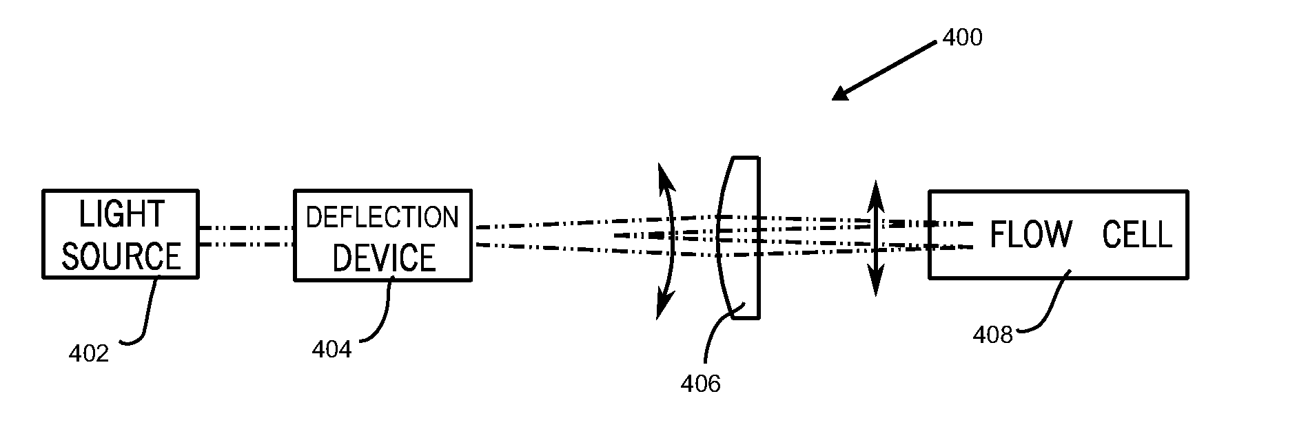
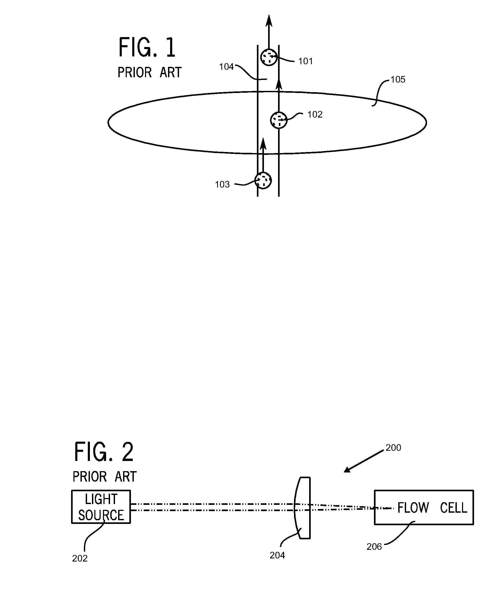
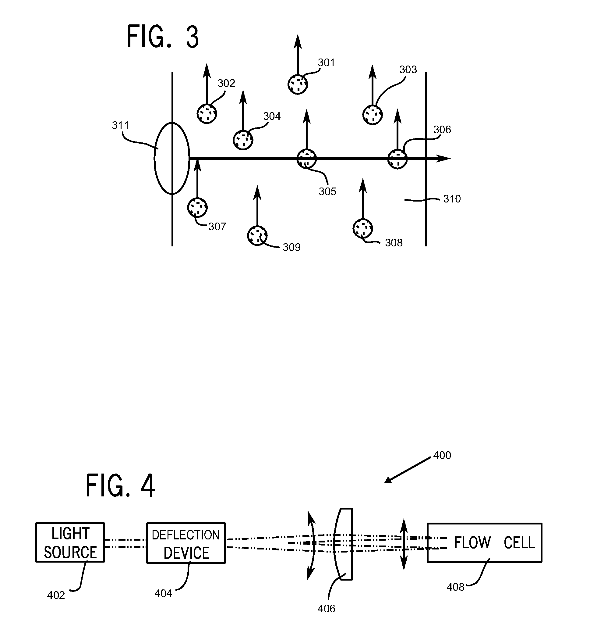
[0016]In a conventional flow cytometer, the stationary laser beam, generally significantly widened in the horizontal direction, intersects the comparatively narrow flowing sample stream, interacting with the cells or other particles therein and resulting in scattering or fluorescent signals that can be detected. According to the method described herein, the sample stream is given a width greater than that of a sample stream in a conventional hematology analyzer, thereby increasing the flow rate of cells through the flow cell. Referring to Eq. 1, this widening operation, in effect, increases the transverse dimension xstream of the sample stream, thereby increasing n by a proportional amount. However, this widening operation also increases the likelihood of potential coincidences.
[0017]In order to limit coincidences to acceptable levels, the spot of focused light from the light beam is reduced in the horizontal dimension so as to intercept only a portion of the resulting sample stream. Because the coincidences are governed by the magnitude of the volume of the sample stream illuminated at any one time by the laser beam, reducing the width of the laser beam to intersect only a portion of the transverse horizontal extent of the sample stream also reduces the magnitude of the illuminated volume. Such reduction is gauged to recover the size of the illuminated volume in the original, conventional design, where the coincidence rates are known and acceptable.

Problems solved by technology

However, this widening operation also increases the likelihood of potential coincidences.

Method used


Image

  • Method and apparatus for rapidly counting and identifying biological particles in a flow stream
  • Method and apparatus for rapidly counting and identifying biological particles in a flow stream
  • Method and apparatus for rapidly counting and identifying biological particles in a flow stream

Examples


Embodiment Construction

[0037]As used herein, the expression “laser rastering” refers to the novel method and apparatus described herein. However, it should be noted that the term “laser” is intended to include any source of light suitable for use in this invention. Such sources of light include, but are not limited to, lasers, light-emitting diodes (LEDs), arc lamps, plasmas, and any other source of light that is capable of providing sufficient brightness, stability or reproducibility or both stability and reproducibility of intensity and wavelength, and spectral purity. Likewise, in the description that follows, a laser will be referred to as an example of a suitable source of light, without implying that other sources of light are not included in the description of this invention. As used herein, the term “deflect” means to move a beam of light across a sample stream in a flow cell. Alternate expressions used herein which are intended to have substantially the same meaning as “deflect” include “scan” an...


PUM


Abstract

A method for increasing the throughput, or the precision, or both the precision and the throughput, of a flow cytometer, or of a hematology analyzer employing a flow cytometer, by utilizing the technique of laser rastering. Laser rastering involves sweeping a laser beam across a flowing sample stream in a hematology analyzer. An apparatus suitable for carrying out the method of this invention comprises an optical module comprising a source of light, a scanning device, a lens or system of lenses, a flow cell, detectors, and filters; and an electronic module comprising preamplifiers, analog signal conditioning elements, analog-to-digital converters, field-programmable gate arrays, digital signal processing elements, and data storage elements.

Description

[0001]This application claims priority to the U.S. Provisional Application Ser. No. 60 / 877,874, filed Dec. 29, 2006.BACKGROUND OF THE INVENTION[0002]1. Field of the Invention[0003]This invention relates to flow cytometers and hematology analyzers, and, more particularly, to hematology analyzers that count and identify biological cells using light scattering and fluorescence techniques in an optical flow cell.[0004]2. Discussion of the Art[0005]Flow cytometry is a technique for counting, examining, and sorting microscopic particles suspended in a stream of fluid. Flow cytometry allows simultaneous, multiparametric analysis of the physical and / or biochemical characteristics of single cells flowing through an optical / electronic detection apparatus. When used in hematology analyzers, flow cytometry enables the precise counting of cells in a measured volume of blood or other biological fluid sample and the identification of those cells based on the use of light scattering and / or fluoresc...

Claims


Application Information

Patent Timeline
IPC IPC(8): G01N21/00
CPCG01N15/0205G01N15/0227G01N15/1459G01N2015/1493G01N2015/025G01N2015/1452G01N2015/1486G01N15/1463G01N15/1433
Inventor VACCA, GIACOMOGOLDBLATT, NORMAN R.YEE, MICHAEL W.
Owner ABBOTT LAB INC
Learn More