
Reflecting Mirror

a technology of reflecting mirrors and mirrors, applied in the field of reflecting mirrors, can solve the problems of poor mechanical strength, film adhesion, moisture resistance, other properties of aluminum reflective layers, and the exfoliation of aluminum reflective layers from the substrate, and achieve satisfactory mechanical strength in terms of scratch resistance, enhanced adhesion, and satisfactory film adhesion to the substra

Inactive Publication Date: 2008-07-03
KONICA MINOLTA OPTO
View PDF8 Cites 10 Cited by
  • Summary
  • Abstract
  • Description
  • Claims
  • Application Information

AI Technical Summary

Benefits of technology

"The present invention provides a reflecting mirror that has good adhesion and scratch-resistance in high-temperature and high-humidity environments. This is achieved by using an adhesive layer made of silicon dioxide and aluminum oxide, a reflective layer made of aluminum, and a dielectric layer made of a low-refraction layer and a high-refraction layer. The low-refraction layer contains silicon dioxide, while the high-refraction layer is made of a mixture of titanium oxide and lanthanum oxide. The combination of these layers enhances film adhesion and scratch-resistance in the high-temperature, high-humidity environment."

Problems solved by technology

Inconveniently, however, aluminum, when used in the form of single-layer film, is poor in mechanical strength, film adhesion, moisture-resistance, and other properties; it is therefore common to lay a protective layer on a reflective layer of aluminum to form multiple-layer film so as to obtain satisfactory mechanical strength, film adhesion, moisture-resistance.
Inconveniently, however, a reflecting mirror fabricated according to this conventional technology, when used in the optical path of an optical system in a high-temperature environment as in a projector equipped with a light source, suffers from exfoliation of the aluminum reflective layer from the substrate and opacity resulting from deposition of moisture.

Method used


Image

  • Reflecting Mirror
  • Reflecting Mirror
  • Reflecting Mirror

Examples


examples

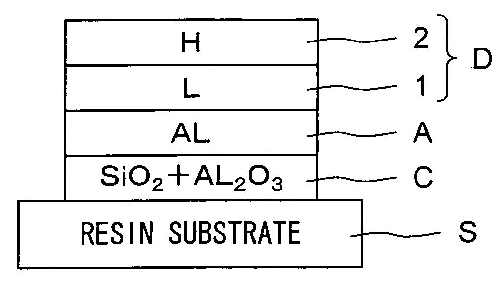
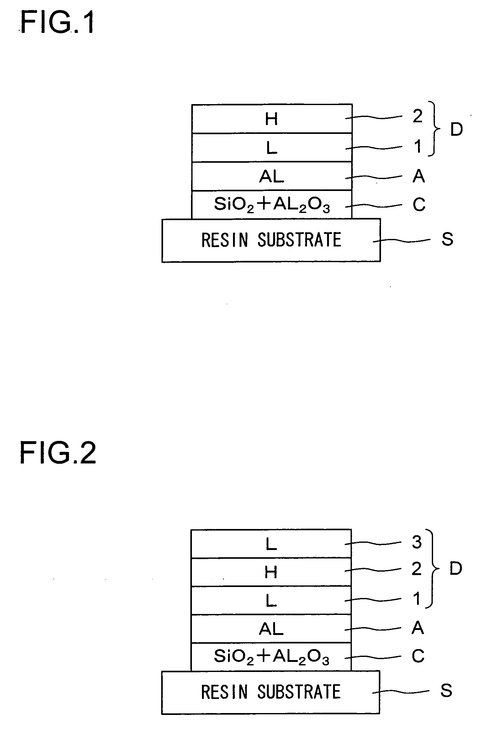
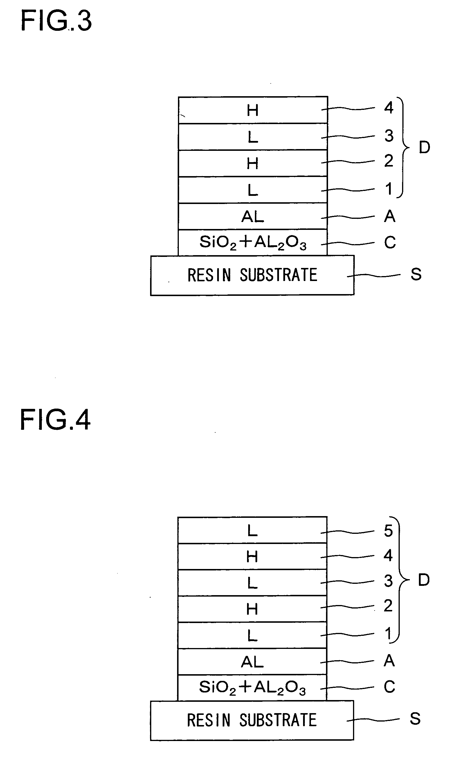
[0027]Hereinafter, as more specific examples of implementation of the present invention, Practical Examples 1 to 11, shown in Table 1, will be presented in comparison with Comparative Examples 1 to 6, shown in Table 2. Here, the materials are assumed to be as follows: TiO2+La2O3 represents a compound of titanium oxide and lanthanum oxide having the composition La2Ti2Ox(x=6.3 to 6.7); SiO2+Al2O3 represents a mixture of silicon dioxide and aluminum oxide; Al represents aluminum; SiO2 represents silicon dioxide; TiO2+Ta2O5 represents a mixture of titanium oxide and tantalum oxide; and TiO2 represents titanium oxide.

[0028]In the reflecting mirror of Practical Example 1, on a substrate of polyolefin resin, a layer of a mixture of 95% by mol of silicon dioxide and 5% by mol of aluminum oxide is formed (an adhesive layer). On the adhesive layer, a reflective layer of aluminum is formed. On the reflective layer, a dielectric layer is formed that is formed of, from the substrate side thereof...


PUM

PropertyMeasurementUnit
thicknessaaaaaaaaaa
thicknessaaaaaaaaaa
thicknessaaaaaaaaaa

Abstract

In a reflecting mirror, an adhesive layer formed of a mixture of silicon dioxide and aluminum oxide is formed between a substrate and an aluminum reflective layer, and, on the aluminum reflective layer, a dielectric layer is formed that has, laid one after another on the aluminum reflective layer, a low-refraction layer containing silicon dioxide and a high-refraction layer formed of a compound of titanium oxide and lanthanum oxide.

Description

[0001]This application is based on Japanese Patent Application No. 2006-351064 filed on Dec. 27, 2006, the contents of which are hereby incorporated by reference.BACKGROUND OF THE INVENTION[0002]1. Field of the Invention[0003]The present invention relates to a reflecting mirror disposed in an optical path in an optical apparatus such as a camera or a projector, and more particularly to a reflecting mirror suitable for use in an apparatus, such as a projector, that is used in a high-temperature environment.[0004]2. Description of Related Art[0005]Aluminum is used as a reflective material in a reflecting mirror employed in an optical apparatus. Inconveniently, however, aluminum, when used in the form of single-layer film, is poor in mechanical strength, film adhesion, moisture-resistance, and other properties; it is therefore common to lay a protective layer on a reflective layer of aluminum to form multiple-layer film so as to obtain satisfactory mechanical strength, film adhesion, m...

Claims


Application Information

Patent Timeline
Patent Type & Authority Applications(United States)
IPC IPC(8): G02B5/08
CPCG02B5/0858
Inventor NOSE, MASAAKITSUKAMOTO, AKIRATERAMOTO, MIYUKITOKUHIRO, SETSUO
Owner KONICA MINOLTA OPTO
Learn More