Eureka AIR delivers breakthrough ideas for toughest innovation challenges, trusted by R&D personnel around the world.

Variable Program and Program Verification Methods for a Virtual Ground Memory in Easing Buried Drain Contacts

a virtual ground memory and buried drain technology, applied in static storage, digital storage, instruments, etc., can solve the problems of large vt distribution of erase state, difficult to erase, and high threshold cell charge loss and low threshold cell charge gain, so as to ease the buried drain contact induced operation and increase the retention window

Active Publication Date: 2008-07-03
MACRONIX INT CO LTD
View PDF19 Cites 9 Cited by
  • Summary
  • Abstract
  • Description
  • Claims
  • Application Information

AI Technical Summary

Benefits of technology

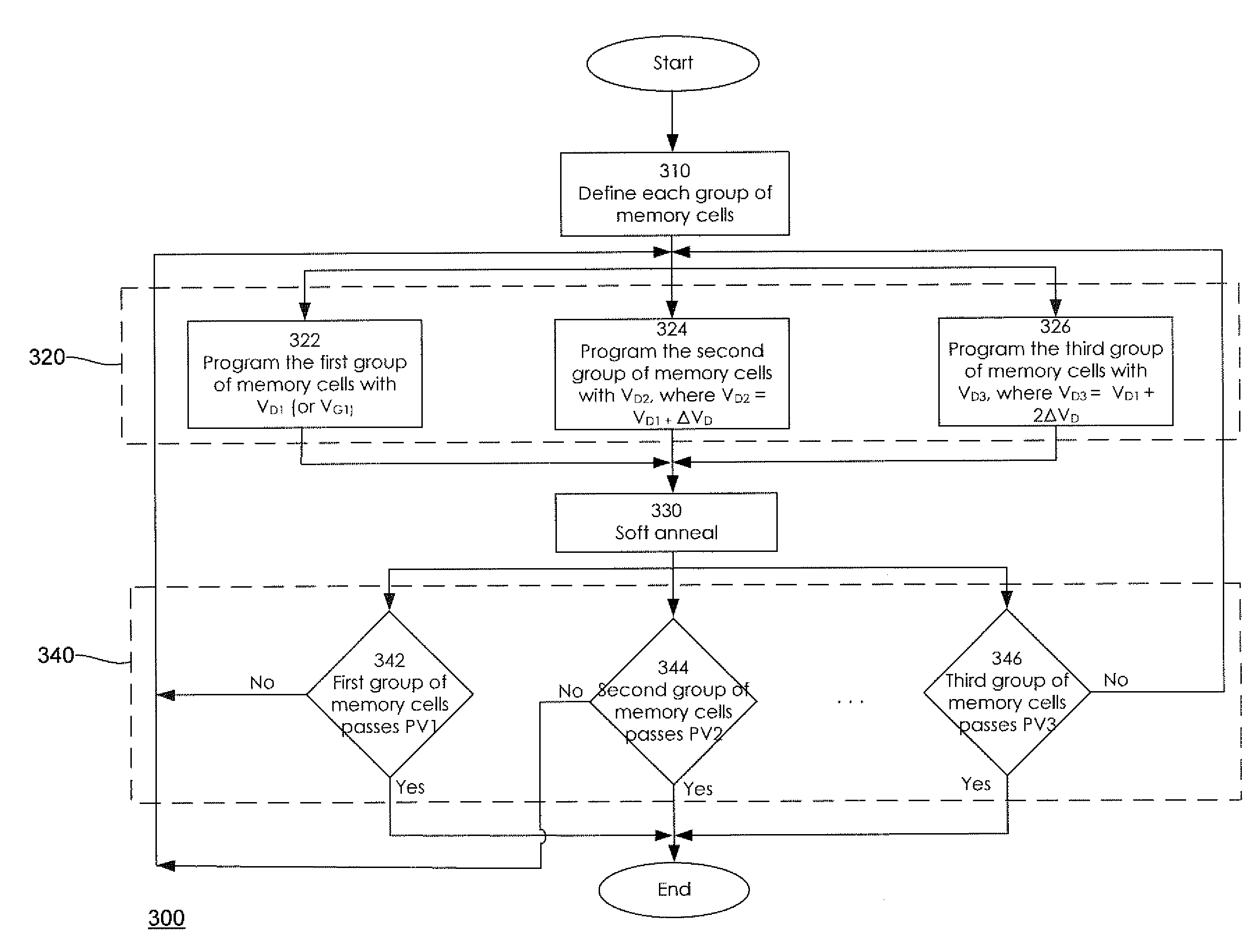
[0012]In a first aspect of the invention, a program operation method provides varying program biases which are applied to different groups of memory cells. The program biases can be supplied as drain bias voltages or gate bias voltages. The program biases vary depending on which group of memory cells are programmed. In one embodiment a first drain voltage VD1 is applied to the first group of memory cells M0 and Mn. A second drain voltage VD2 is applied to the second group of memory cells M1 and Mn-1, where VD2=VD1+ΔVD. A third drain voltage VD3 is applied to the third group of memory cells M2 and Mn-2 where VD3=VD1+2ΔVD. The varying drain voltages of VD1, VD2, VD3 are intended as an illustration. Other voltage settings, relationships, modifications or adaptations between VD1, VD2, VD3, such as the second drain voltage VD2 being about the same voltage as the third drain voltage VD3, or the second and third drain voltages VD2, VD3 being set at a predetermined voltage value, can be practiced without departing from the spirit of the present invention. In an alternative embodiment, a gate bias voltage VG can be applied to the different groups of memory cells instead of being applied with a drain voltage VD. The varying drain bias voltages ease the bit line loading that is induced by a program current. When the drain bias voltages of the different groups of memory cells are similar, the threshold voltage Vt distribution is contained and the widening of the threshold voltage Vt by a loading effect can be minimized.
[0014]Broadly stated, a method for programming a virtual ground memory having a plurality of bit lines, a bit line connecting a plurality of memory cells M0 through Mn with the memory cell M0 at a first location on the bit line, the memory cell M1 at a second location on the bit line, the memory cell M2 on a third location on the bit line, the memory cell Mn-2 at a fourth location on the bit line, the memory cell Mn-1 at a fifth location on the bit line, the memory cell Mn at a sixth location on the bit line, the plurality of memory cells M0 through Mn divided into a first set of memory cells and a second set of memory cells comprises programming the first set of memory cells by applying a first bias voltage to the first set of memory cells, the first set of memory cells including memory cell M0 at the first location on the bit line and the memory cell Mn at the sixth location on the bit line, the memory cell M0 at the first location and the memory cell Mn at the sixth location are the contact cells on the bit line; and programming the second set of memory cells by applying a second bias voltage to the second set of memory cells, the second set of memory cells including the memory cell M1 at the second location on the bit line and the memory cell Mn-1 at the fifth location on the bit line, the memory cells M1 and Mn-1 located away from the contacts; wherein the second bias voltage has a voltage value that is sufficiently larger than the first bias voltage to ease the loading induced program distribution on the bit line.
[0015]Advantageously, the present invention provides methods that ease the buried drain contact induced operation and enhance the reliability of a flash memory. The present invention also advantageously provides a tighter program distribution. The present invention further provides a larger reliability window by programming the contact cells to a higher program voltage threshold.

Problems solved by technology

However, the hot hole injection causes oxide damage, leading to charge loss in the high threshold cell and charge gain in the low threshold cell.
This difference in erase speed results in a large Vt distribution of the erase state, where some of the cells become hard to erase and some of them are over-erased.
Thus the target threshold Vt window is closed after many program and erase cycles and poor endurance is observed.
This phenomenon will become more serious as the technology continues to scale down.
Evaluating the endurance and retention of a charge trapping memory array, the lack of uniformity in eraseability causes a margin loss due to cycling and baking.
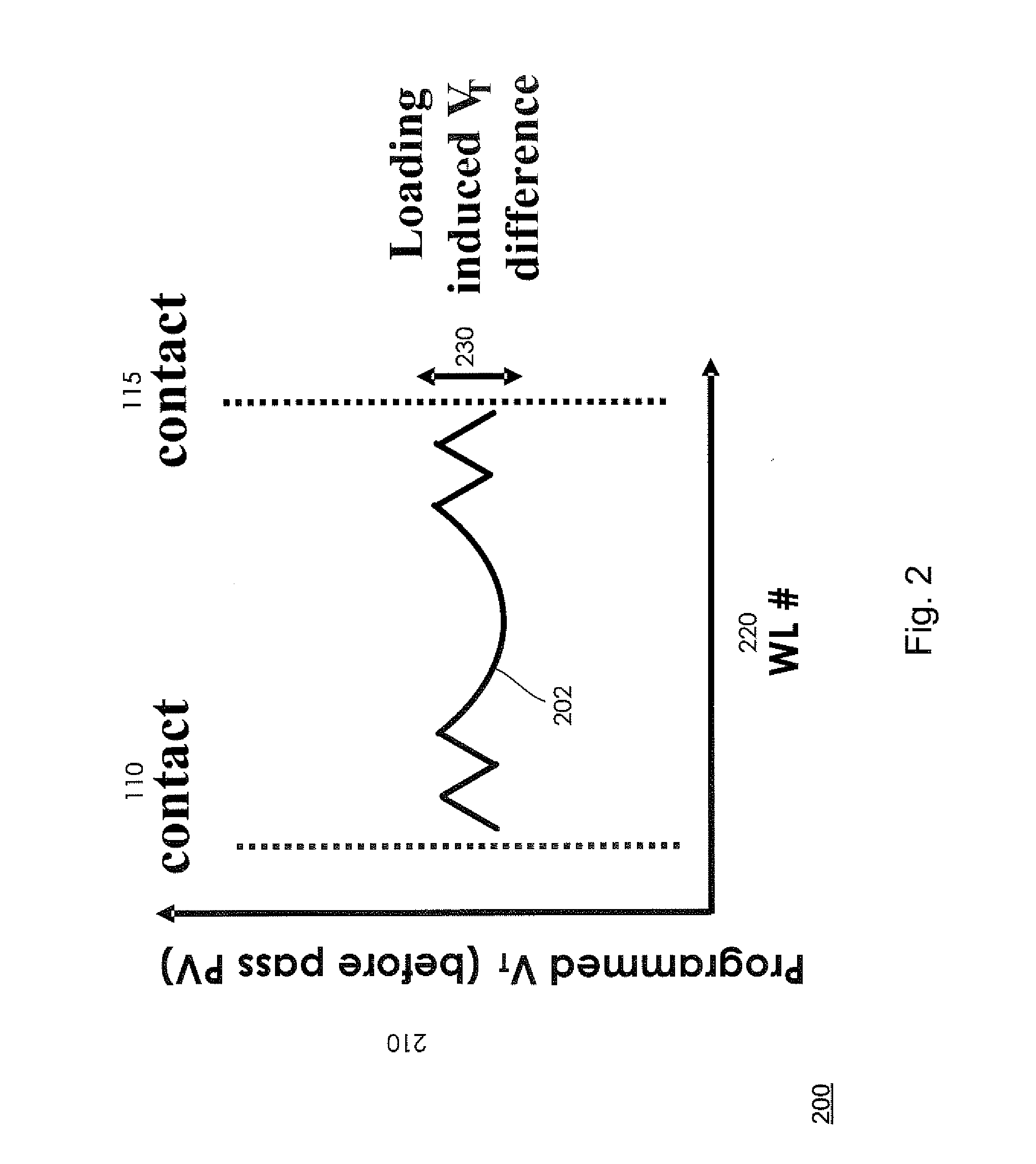
Such an algorithm produces a significant loading induced voltage threshold differential between flash memory cells.

Method used


Image

  • Variable Program and Program Verification Methods for a Virtual Ground Memory in Easing Buried Drain Contacts
  • Variable Program and Program Verification Methods for a Virtual Ground Memory in Easing Buried Drain Contacts
  • Variable Program and Program Verification Methods for a Virtual Ground Memory in Easing Buried Drain Contacts

Examples


Embodiment Construction

[0022]A description of structural embodiments and methods of the present invention is provided with reference to FIGS. 1-4. It is to be understood that there is no intention to limit the invention to the specifically disclosed embodiments but that the invention may be practiced using other features, elements, methods and embodiments. Like elements in various embodiments are commonly referred to with like reference numerals.

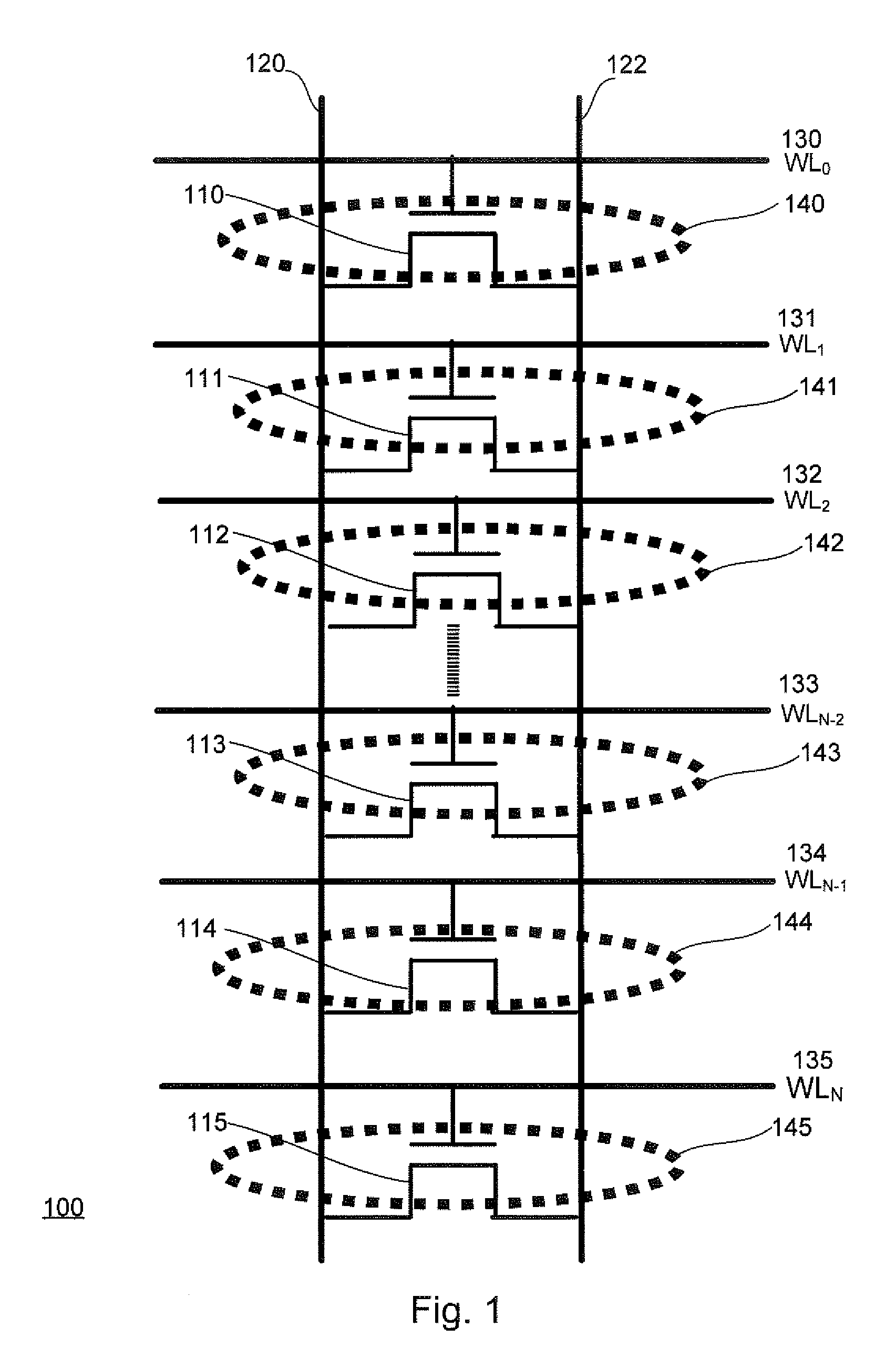
[0023]Referring now to FIG. 1, there is shown a simplified circuit diagram illustrating a memory circuit 100 that groups a plurality of memory cells along a bit line with intersecting word lines and applies variable bias voltages along the bit line. The memory circuit 100 comprises a plurality of transistors 110, 111, 112, 113, 114, 115 that have their respective drain and source regions connected to two parallel bit lines 120, 122. The first bit line 120 and the second bit line 122 intersect with word lines WL0 130, WL1 131, WL2 132, WLN-2 133, WLN-1 134, WLN 135...


PUM


Abstract

Methods for programming and program verification of a flash memory are described that ease the buried drain contact induced operation and increase the retention window. In a first aspect of the invention, a program operation method provides varying program biases which are applied to different groups of memory cells. The program biases can be supplied as drain bias voltages or gate bias voltages. The program biases vary depending on which group of memory cells is programmed. In one embodiment, a first drain voltage VD1 is applied to the first group of memory cells M0 and Mn. A second drain voltage VD2 is applied to the second group of memory cells M1 and Mn-1, where VD2=VD1+ΔVD. In a second aspect of the invention, a plurality of program verification voltage levels are selected to verify that the memory cells pass the program voltage levels.

Description

BACKGROUND OF THE INVENTION[0001]1. Field of the Invention[0002]The present invention relates generally to electrically programmable and erasable memory and, more particularly, to methods for easing the buried contact induced operation and increasing the reliability window of a nitride trapping memory.[0003]2. Description of Related Art[0004]Electrically programmable and erasable nonvolatile memory technologies based on charge storage structures known as Electrically Erasable Programmable Read-Only Memory (EEPROM) and flash memory are used in a variety of modern applications. A flash memory is designed with an array of memory cells that can be independently programmed and read. Sense amplifiers in a flash memory are used to determine the data value or values stored in a nonvolatile memory. In a typical sensing scheme, an electrical current through the memory cell being sensed is compared to a reference current by a current sense amplifier.[0005]A number of memory cell structures are...

Claims


Application Information

Patent Timeline
IPC IPC(8): G11C16/04G11C16/06
CPCG11C16/10G11C16/3459G11C16/3454
Inventor CHEN, MING-SHIANGLU, WEN-PINHUANG, I-JENCHIN, CHI YUANZOUS, NIAN-KAI
Owner MACRONIX INT CO LTD
Why Eureka
Eureka Blog
Learn More