
Method of Estimating Stable State Membrane Filtration Flux

a membrane filtration flux and stable state technology, applied in the field of method of estimating stable state membrane filtration flux, can solve the problems of reducing flux rapidly or gradually, being completely impossible to estimate the stable state flux value in advance, and the method cannot be used in a very narrow water quality rang

Active Publication Date: 2008-07-10
ASAHI KASEI CHEM CORP
View PDF1 Cites 7 Cited by
  • Summary
  • Abstract
  • Description
  • Claims
  • Application Information

AI Technical Summary

Benefits of technology

[0014]It becomes possible to estimate the maximum value of the flux during long-term stable operation including cleaning conditions of a membrane filtration plant very simply from liquid flow data for a short initial membrane filtration period. As a result, there is no longer any need to carry out long-term test operation when designing a new membrane filtration plant.

Problems solved by technology

The nature of the liquid to be treated in a membrane filtration plant varies between membrane filtration plants, and it is often the case that various substances contained in the liquid cause so-called fouling such as clogging of the membranes so that the flux decreases rapidly or gradually.
However, the stable state flux during actual operation is affected by the type of substances contained in, the nature of particles in, and the concentration and so on of the liquid to be treated with pre-treatment included, and furthermore is considered to be affected in a complex way by various conditions such as the filtration membrane characteristics, interaction between substances contained in the liquid to be treated and the filtration membranes, the filtration membrane cleaning conditions, the operating conditions, and so on.
Conventionally, due to such complex interactions, it has been considered to be completely impossible to estimate the stable state flux value in advance.
However, this method can only be used in a very narrow water quality range, and hence is not very practicable.
However, in that invention, DOC, E260, and turbidity must be analyzed, which is complicated.
Moreover, the cause of organic contamination is specified as being humic matter, the extent of contamination being calculated purely from the ratio between DOC and E260, and hence in the case that organic matter other than humic matter contributes to membrane contamination, the effect thereof cannot be properly evaluated.

Method used


Image

  • Method of Estimating Stable State Membrane Filtration Flux
  • Method of Estimating Stable State Membrane Filtration Flux
  • Method of Estimating Stable State Membrane Filtration Flux

Examples


example 1

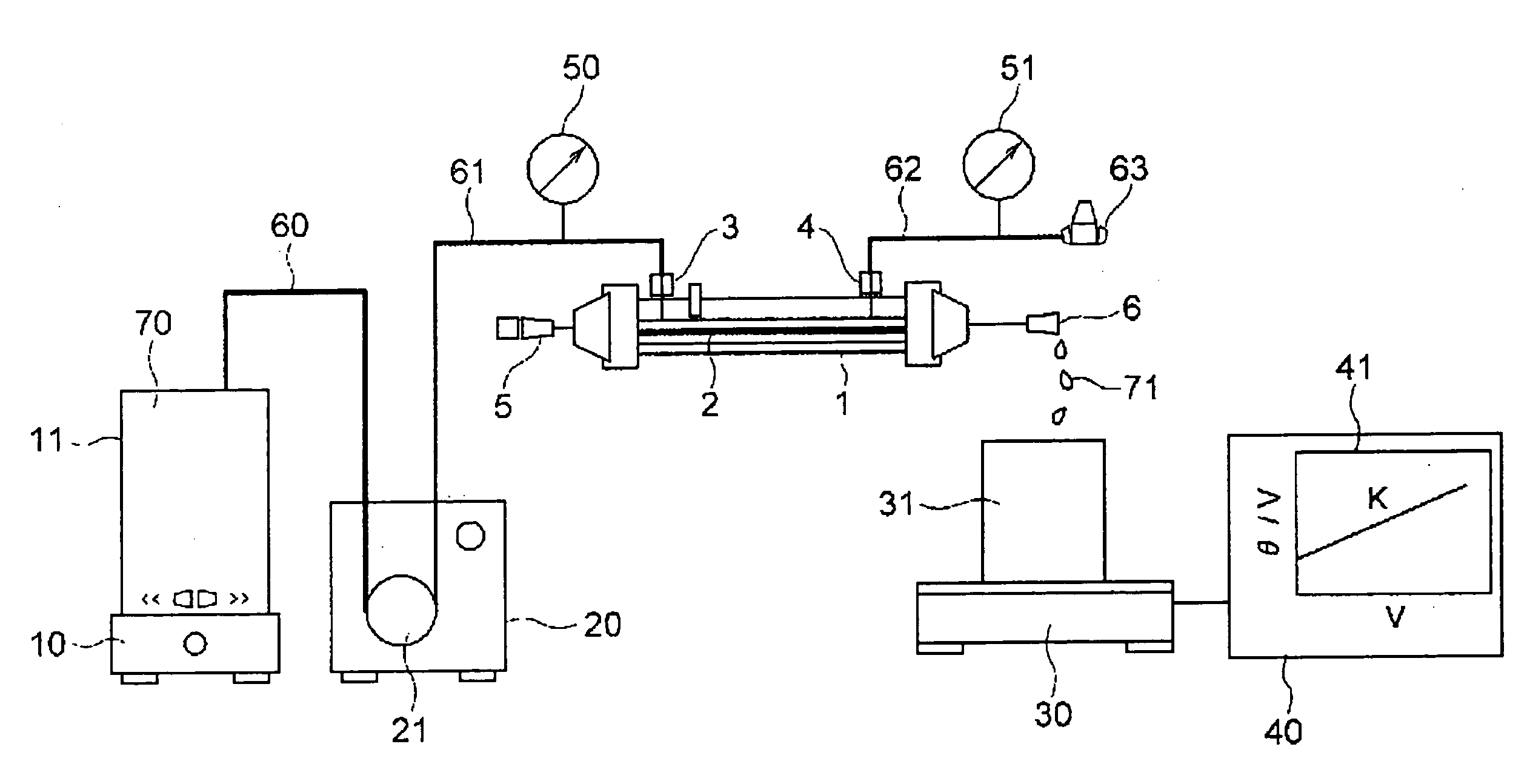
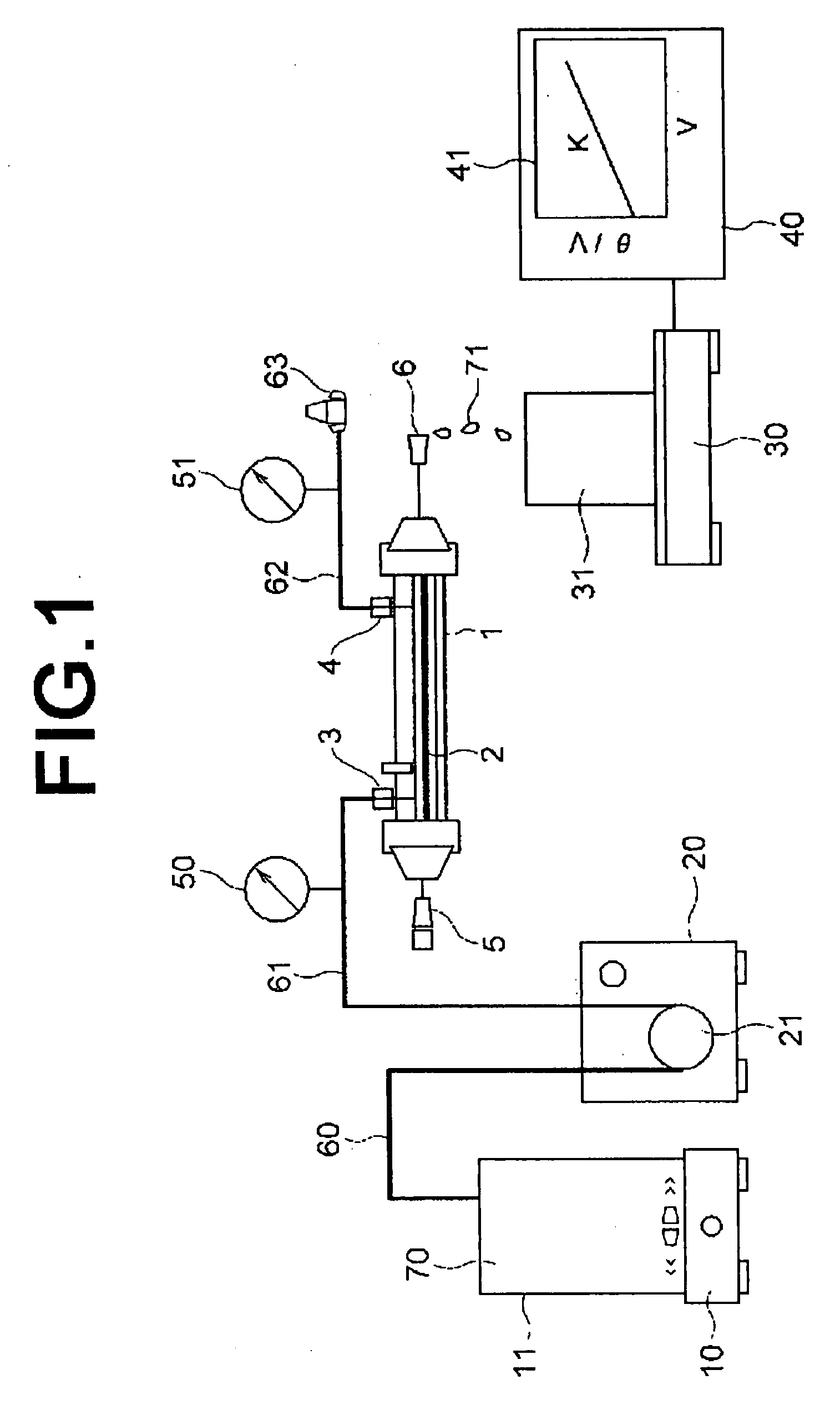
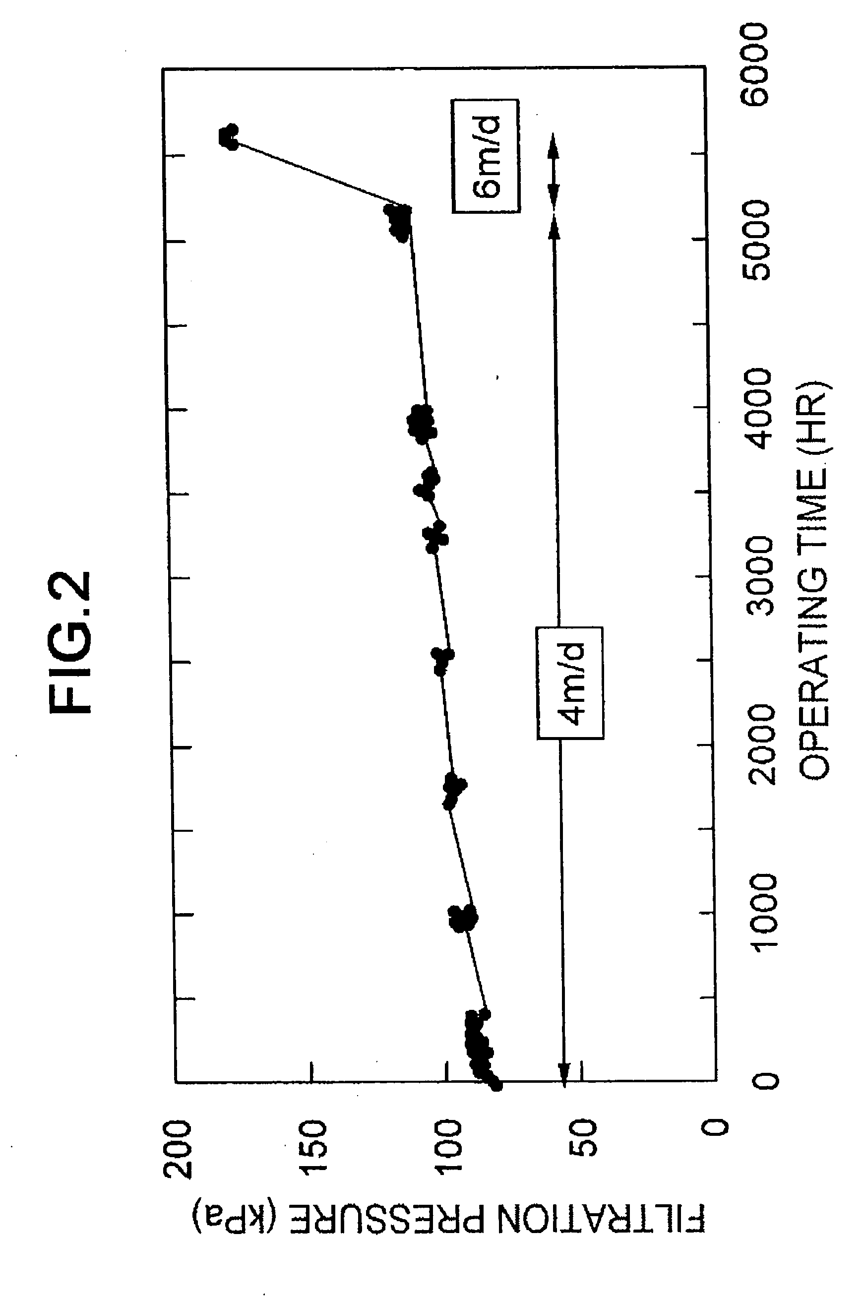
[0059]For a certain sand filtration facility for river water, before constructing a new membrane filtration plant for filtering wastewater during backwashing, the maximum stable flux value was estimated. The turbidity of the wastewater was relatively high at 100 degree. It was decided to select a hollow fiber type precise filtration membrane module made by Asahi Kasei Chemicals Corporation (model number UNA-620A, membrane area 50 m2) as the membrane module, which was considered to be suitable from the required throughput and so on, and the stable operating time period up to chemical cleaning was set to 6 months. Moreover, a total of 30 minutes comprising 28.5 minutes of filtration operation, 1 minute of air scrubbing with backwashing, and 30 seconds of flushing was taken as a unit process, this constituting standard operating conditions, and operation was carried out by repeating this unit process. During the air scrubbing with backwashing, sodium hypochlorite was added to a concent...

reference example 1

[0066]It was attempted to estimate the maximum value of the flux in a stable state using the SDI (silt density index) measurement method. Using a precise filtration filter of pore size 0.45 μm (made by Millipore, trade name HAWP 47 mm φ) as a filter, the liquids to be treated in the membrane filtration plants (A), (B) and (C) in working example 1 were each subjected to filtration. As the filtration conditions, the filtration pressure was made to be fixed at 210 kPa, and the filtration flow rate measurement time interval was made to be 15 minutes. First, the time required to filter 500 ml of the liquid to be treated at the start of the filtration was measured. This was taken as t0. Next, the filtration was continued, and after the measurement time interval of 15 minutes had elapsed from the start of the filtration, the time required to filter 500 ml of the liquid to be treated was again measured. This was taken as t15. The SDI was calculated from these measured values and the followi...


PUM


Abstract

It is an object of the present invention to provide a method of estimating the maximum value of the flux during long-term stable operation including cleaning of a membrane filtration plant based on measured data of a membrane filtration characteristic during initial membrane filtration. The present invention provides a method in which the maximum flux during stable operation of a new membrane filtration plant for which a membrane module and operating conditions have been specified is estimated from a measured value A of an initial membrane filtration characteristic measured using a liquid to be treated in and a membrane of a membrane module of the new membrane filtration plant, an empirical value of a maximum flux during stable operation of each of a plurality of existing membrane filtration plants having the same or a similar membrane module and operating conditions, and a measured value B of the initial membrane filtration characteristic measured using a liquid to be treated in and a membrane of a membrane module of each of the existing membrane filtration plants.

Description

TECHNICAL FIELD[0001]The present invention relates to a method of estimating the value of a membrane filtration flux in its stable state, required for designing a new membrane filtration plant, based on initial membrane filtration test data.BACKGROUND ART[0002]In a membrane filtration plant that uses filtration membranes such as ultrafiltration membranes or precise filtration membranes, a liquid to be separated is passed through a membrane module, and pressure is applied to the liquid from outside the membrane module. Desired filtration is then carried out under conditions at which a certain flux can be obtained, based mainly on the size of the pores in the membranes.[0003]The nature of the liquid to be treated in a membrane filtration plant varies between membrane filtration plants, and it is often the case that various substances contained in the liquid cause so-called fouling such as clogging of the membranes so that the flux decreases rapidly or gradually. In a membrane filtrati...

Claims


Application Information

Patent Timeline
Patent Type & Authority Applications(United States)
IPC IPC(8): G01F1/00
CPCB01D61/14B01D61/22B01D65/10C02F1/444B01D2311/22B01D2325/28B01D2311/16B01D65/00
Inventor OGAWA, TAKASHIMORI, YOSHIHIKO
Owner ASAHI KASEI CHEM CORP
Learn More