Tracheostomy Tube

a tracheostomy tube and tube body technology, applied in the field of tracheostomy tube, can solve the problems of troublesome operation of applying lubricant to the lumen body or the cuff, tube can be easily detached, sputum or food can be easily accumulated,

Inactive Publication Date: 2008-07-10
TYCO HEALTHCARE GRP LP
View PDF18 Cites 25 Cited by
  • Summary
  • Abstract
  • Description
  • Claims
  • Application Information

AI Technical Summary

Benefits of technology

[0009]In the tracheostomy tube having the above-mentioned structure, the coating layer exhibiting the surface lubricity in moisture is formed on the surface of the tracheostomy tube. As a result, when the tracheostomy tube is fitted to or detached from the incision site of a patient, it is possible to easily perform the operation of fitting or detachment by performing a simple operation such as dipping the surface of the tracheostomy tube into water. The coating layer exhibiting the surface lubricity in moisture is formed on the inner surface of the lumen body in which the airway securing lumen is formed.
[0010]As a result, when the inner surface of the lumen body gets wet by vapor or spit at the time of the patient's respiration, the surface lubricity is exhibited. Accordingly, sputum or the like is not easily attached to the inner surface of the lumen body. As a result, it is possible to prevent sputum or foods from being accumulated in the lumen body. In this case, the surface of the tracheostomy on which the coating layer is formed includes at least the surface of the lumen body or the cuff, that is, a portion coming in contact with the incision site of the patient when the tracheostomy tube is fitted or detached.
[0012]The mixture exhibits the surface lubricity in moisture and thus allows the surface of the tracheostomy tube or the inner surface of the lumen body in which the airway securing lumen is formed to easily slide. Accordingly, since the insertion resistance when the tracheostomy tube is inserted into the incision site becomes small, the tracheostomy tube can be easily fitted. Similarly, the tracheostomy tube can be easily detached from the incision site and foreign substances such as sputum is not easily accumulated in the tracheostomy tube. The coating layer made of the mixture can be formed through a simple process such as dipping the constituent base members of the tracheostomy tube in the mixture, without performing any pretreatment such as introduction of a function group, thereby giving the lubricity to the constituent base members of the tracheostomy tube. Since the mixture is low in cost and is widely used, the mixture is easily available.
[0013]In the tracheostomy tube according to the present invention, the coating layer may be made of a mixture of methyl vinyl eter maleic anhydride copolymer and polyether-block-amide. Accordingly, the lubricity can be given to the constituent base members of the tracheostomy tube by the use of a simple process. The coating layer can be formed out of a material which is low in cost, is easily available, and is widely used. By using the mixture, it is possible to obtain the coating layer having high durability.
[0014]In the tracheostomy tube according to present invention, the coating layer may be made of a mixture including polyisocyanate and a mixture including polyvinyl pyrrolidone. Since the coating layer made of the mixtures can be formed on the surface of a constituent base member made of any polyurethane resin, it is possible to form the coating layer having excellent lubricity by making the constituent base members of the tracheostomy tube out of predetermined polyurethane resin.
[0015]In the tracheostomy tube according to the present invention, the coating layer may be formed by depositing a mixture including a solvent in which a material of the tracheostomy tube is poorly soluble. In this case, it is preferable that the main component of the solvent is alcohol such as 2-propanol or ethanol. As a result, it is possible to form the coating layer having excellent lubricity on the surface of the tracheostomy tube or the inner surface of the lumen body in which the airway securing lumen is formed, without melting the respective base members of the tracheostomy tube, specifically, the cuff.

Problems solved by technology

However, in the tracheostomy tube described in Patent Document 1, there is a problem that the operation of applying a lubricant to the lumen body or the cuff is troublesome when the tracheostomy tube is attached to the trachea.
Further, there is a problem in that sputum or foods can be easily accumulated inside the tracheostomy tube.
Similarly, the tracheostomy tube can be easily detached from the incision site and foreign substances such as sputum is not easily accumulated in the tracheostomy tube.

Method used


Image

  • Tracheostomy Tube
  • Tracheostomy Tube

Examples


first embodiment

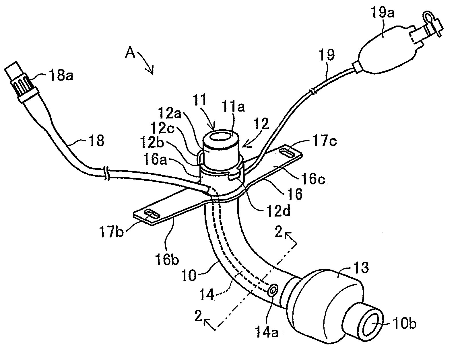
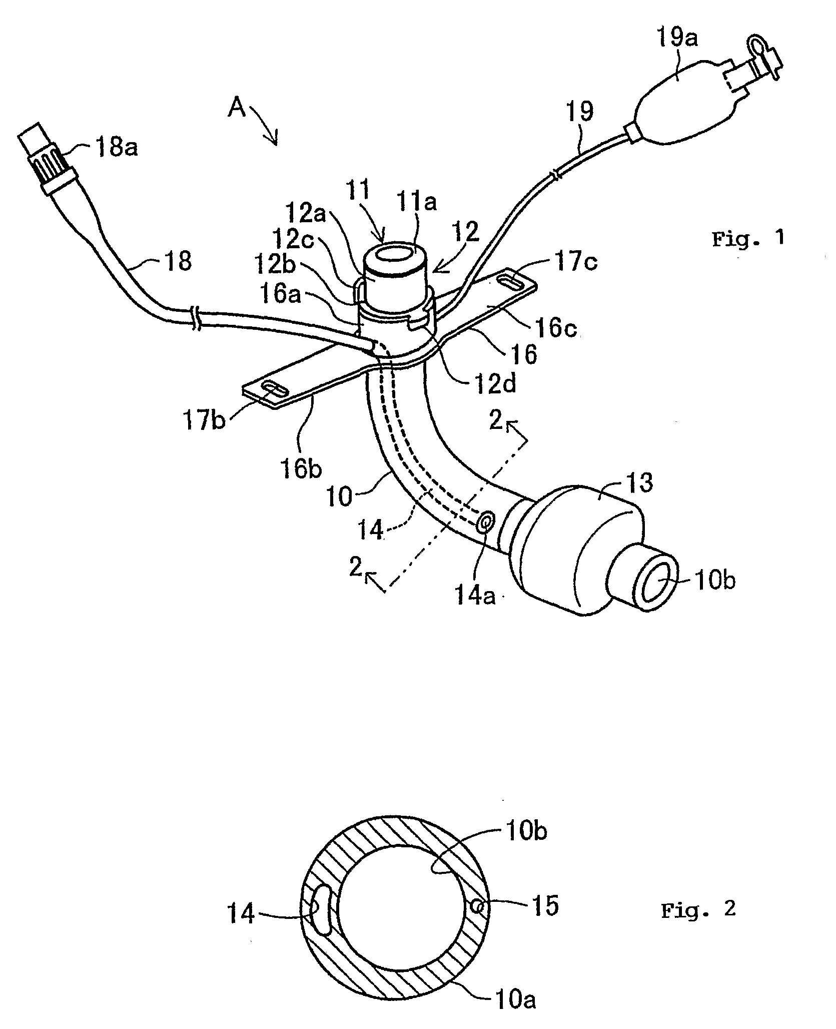
[0033]A mixture solution obtained by adding 20 wt % of fluorine-containing acryl urethane silicon resin to a solution of 2-propanol / tetrahydrofuran (weight ratio=70:30) in which 2 wt % of methylvinyl ether maleic anhydride copolymer (product name: Gauntlets AN-169, made by ISP Co.) is dissolved was prepared. Then, the constituent base members of the tracheostomy tube A were dipped into the mixture solution, thereby coating the surface or the inner surface (inner surface of the airway securing lumen 10b) of the constituent base members of the tracheostomy tube A with the mixture solution. Thereafter, the tracheostomy tube A was obtained by immersing the constituent base members of the tracheostomy tube A in a 0.1N aqueous solution of sodium hydroxide and forming the coating layer on the surface and the inner surface of the constituent base members of the tracheostomy tube A.

second embodiment

[0034]A mixture solution obtained by adding 1 wt % of polyether-block-amide (product name: Pabex 3533, made by ATOFINA Chemicals Ltd. (changed to ARKEMA Yoshitomi Ltd. in 2004)) to a solution of 2-propanol / tetrahydrofuran (weight ratio=70:30) in which 2 wt % of methylvinyl ether maleic anhydride copolymer (product name: Gauntlets AN-169, made by ISP Corporation) is dissolved was prepared. Then, the constituent base members of the tracheostomy tube A were dipped into the mixture solution, thereby coating the surface or the inner surface (inner surface of the airway securing lumen 10b) of the constituent base members of the tracheostomy tube A with the mixture solution. Thereafter, the tracheostomy tube A was obtained by immersing the constituent base members of the tracheostomy tube A in a 0.1N aqueous solution of sodium hydroxide and forming the coating layer on the surface and the inner surface of the constituent base members of the tracheostomy tube A.

third embodiment

[0035]A mixture solution of 2-propanol / tetrahydrofuran (weight ratio=70:30) including 1 wt % of polyisocyanate (product name: Duranate D-101, made by Asahi Kasei Chemicals Corporation) and 2 wt % of polyurethane (product name: Decofrax, made by NOBEON Corporation) was prepared. Then, the constituent base members of the tracheostomy tube A were dipped into the mixture solution, thereby forming a basic coating layer on the surface or the inner surface (inner surface of the airway securing lumen 10b) of the constituent base members of the tracheostomy tube A. Next, a mixture solution of 5% polyvinyl pyrrolidone (K-90, made by GAF Corporation) and 2-propanol / tetrahydrofuran (weight ratio=70:30) was prepared. Thereafter, the tracheostomy tube A was obtained by dipping the constituent base members of the tracheostomy tube A in the mixture solution and coating the surface or the inner surface of the constituent base members of the tracheostomy tube A with the mixture solution to form the c...


PUM


Abstract

To provide a tracheostomy tube which can be easily attached to and detached from an incision site and in which sputum or the like does not readily longer, a tracheostomy tube A includes a lumen body 10 having an airway securing lumen 10b, a connector section 11 formed at the base end portion of the lumen body 10, and a cuff 13 which is formed on the outer circumference of the tip end portion of the lumen body 10 and which can be expanded and contracted. A circumferential wall 10a of the lumen body 10 defines a cuff-expanding lumen 15 which puts the surface portion of the connector section 11 in communication with the inside of the cuff 13. it also defines a suction lumen 14 allowing the surface portion of the connector section 11 to communicate with the surface portion of the lumen body 10. A coating layer exhibiting surface lubricity in moisture is formed on the surface of the tracheostomy tube A and the inner surface of the lumen body 10 in which the airway securing lumen 10b is formed.

Description

TECHNICAL FIELD[0001]The present invention relates to a tracheostomy tube used for a patient having an impaired or deteriorated respiration function.RELATED ART[0002]Conventionally, patients having a deteriorated respiration function have been subjected to such a treatment as performing a tracheostomy and inserting a tracheostomy tube into the incision site. As a result, air can be sent directly to the lungs through a trachea from the outside, not through a throat or a nose, or can be sent to the outside through the trachea from the lungs (for example, see Patent Document 1, as discussed below). In such a tracheostomy tube, a connector section is provided at the base end portion of a lumen body in which an airway securing lumen is formed from the base end portion to the tip end portion and a cuff which is expandable and contractible is provided on the outer circumference of the tip end portion of the lumen body.[0003]A cuff-expanding lumen allowing one side of the surface of the con...

Claims


Application Information

Patent Timeline
Patent Type & Authority Applications(United States)
IPC IPC(8): A61M16/00
CPCA61M16/0434A61M16/0465A61M16/0479A61M16/0497A61M16/0488A61M16/0486
Inventor KUSUNOKI, TAKAOMORIYAMA, MASAKI
Owner TYCO HEALTHCARE GRP LP
Why Eureka
Try Eureka