
Hand-pulling food cutter/mixer

Inactive Publication Date: 2008-07-10
CHAU MEI YING +1
View PDF11 Cites 26 Cited by
  • Summary
  • Abstract
  • Description
  • Claims
  • Application Information

AI Technical Summary

Benefits of technology

[0003]The present utility model is to overcome the above-mentioned defects existed in the prior arts, to provide one hand-pulling food cutter / mixer which has a low production cost, saves energy, and is safe and convenient.
[0012]1. Driven manually, the present utility model is just composed of the lid, the container and the blade assembly, and has a simple structure, a convenient production art and a low production cost. For the blade assembly of the present utility model can be replaced by a stirrer, it can serve not only as a food cutter but also a food mixer, which saves materials greatly.
[0013]2. Driven manually, the present utility model has an increased safety factor and a lower noise while saving energy.
[0014]3. Driven manually, the present utility model is not restricted by the environment, and is easy to use.
[0015]4. That the present utility model can be used not only as a food cutter but also a food mixer makes it convenient to use.

Problems solved by technology

This kind of food cutter or mixer has a relatively complicated construction and a high production cost, and should be used where the electricity is available, moreover, it has a high energy consumption and a certain hidden trouble of safety, and produces very high noises.

Method used


Image

  • Hand-pulling food cutter/mixer
  • Hand-pulling food cutter/mixer
  • Hand-pulling food cutter/mixer

Examples


Embodiment Construction

[0022]In order to understand the technical content of the present utility model more clearly, please refer to FIG. 1˜FIG. 6.

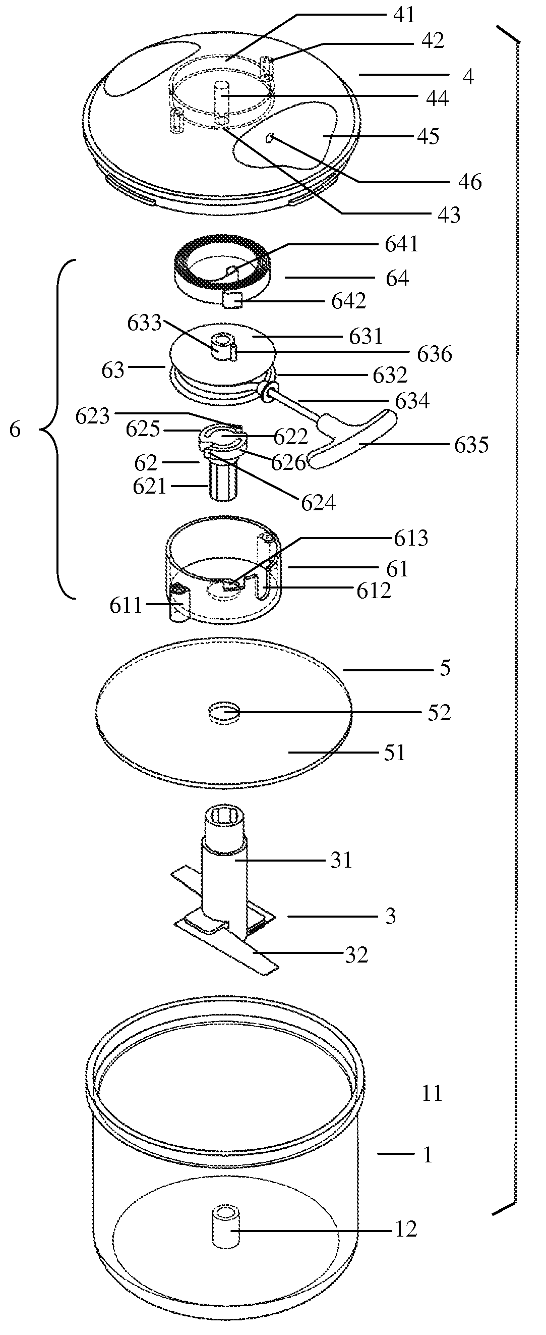
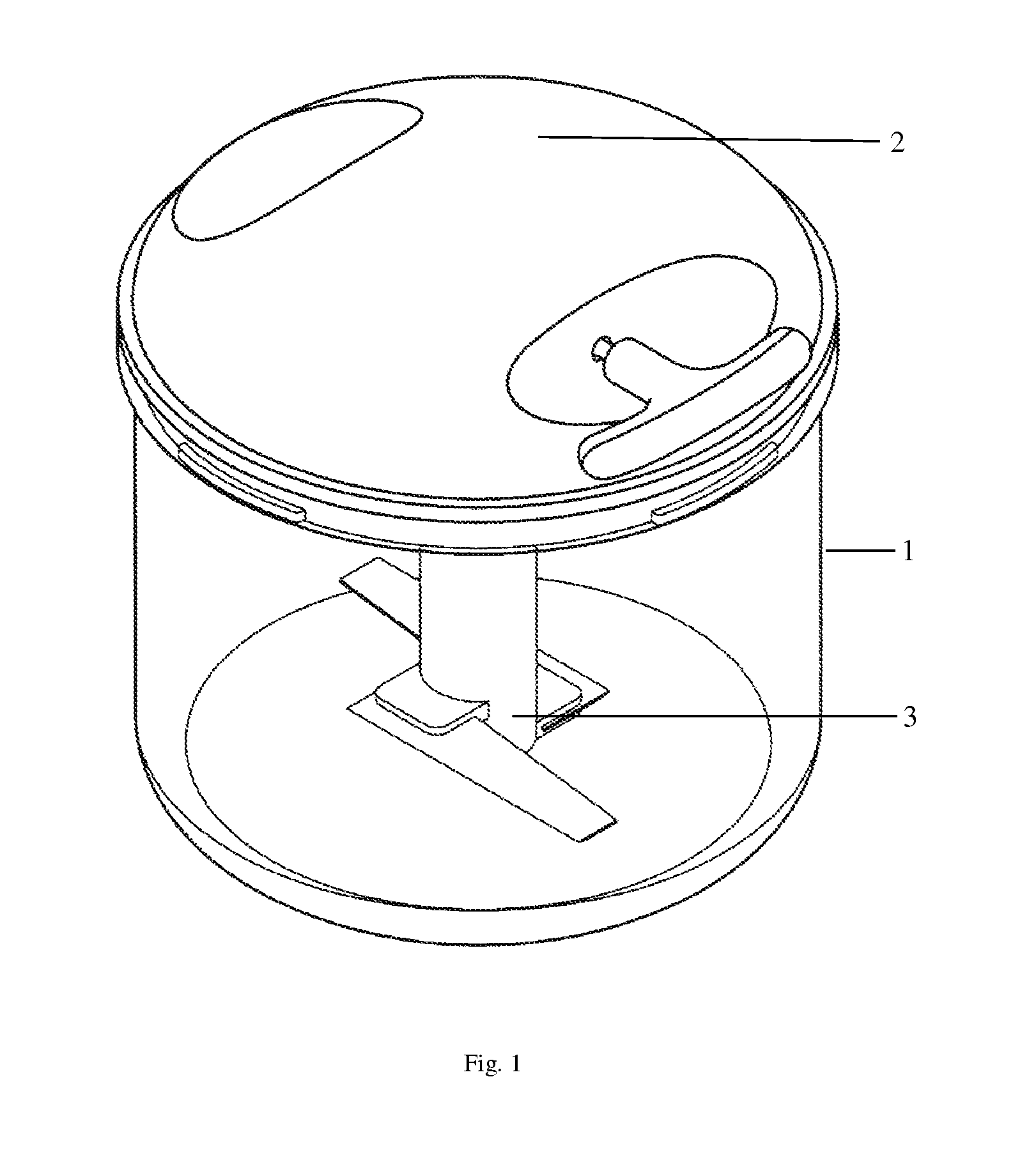
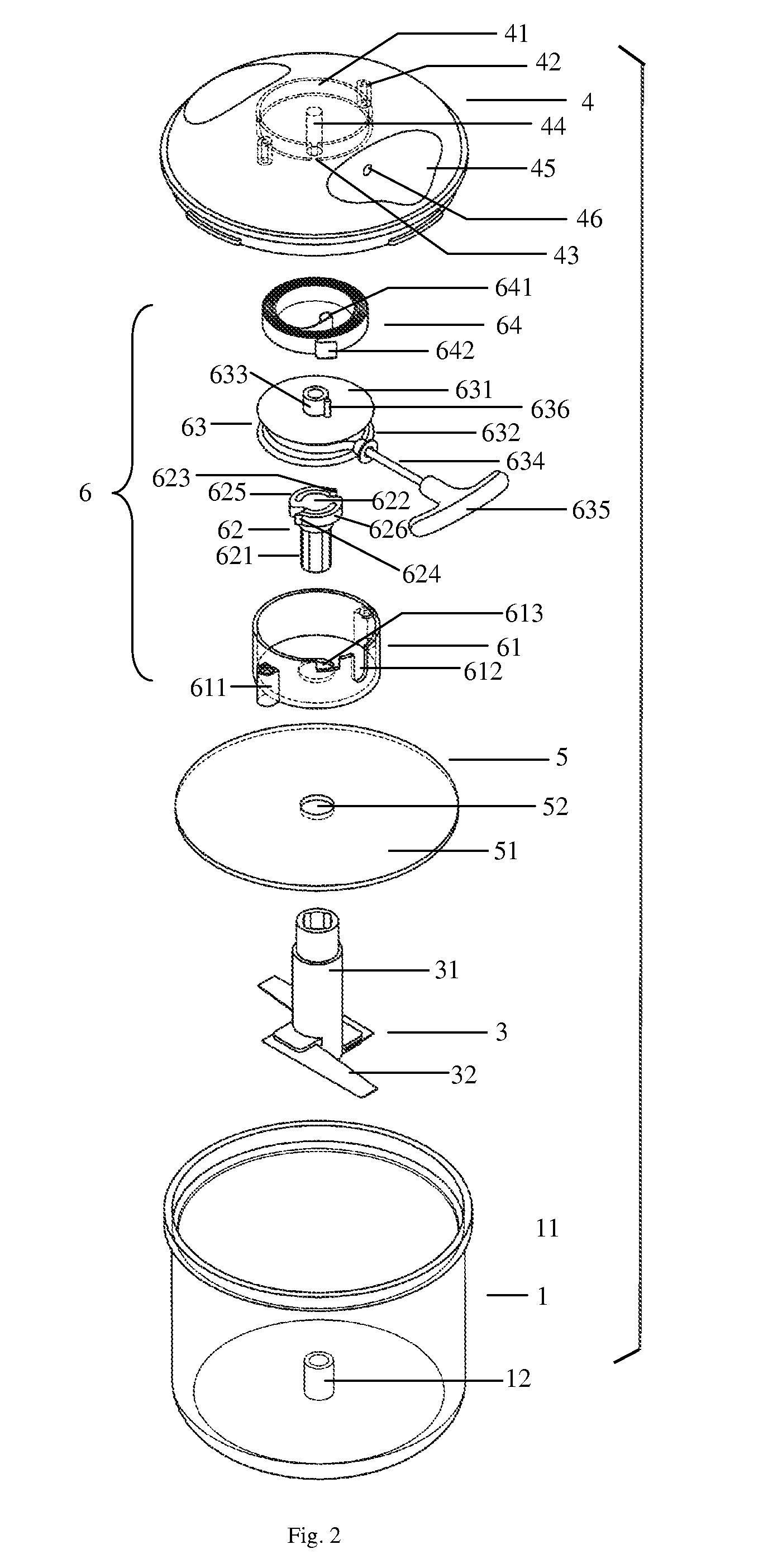
[0023]To overcome the shortcomings of the prior arts, the hand-pulling food cutter / mixer of the present utility model comprises a container 1, a lid 2 on the container 1 and a blade assembly 3 in the container 1, wherein:

[0024]The lid 2 comprises an upper lid 4, a lower lid 5 and a hand-pulling driving mechanism 6 which is between the upper lid 4 and the lower lid 5 and fixed to the upper lid 4.

[0025]The upper lid 4 is a disk protruding upwardly slightly, and its underside surface has an annular ring 41 protruding downwardly outside which there are two column apertures into which bolts can be screwed. The annular ring 41 has an opening 43, and the center of the annular ring 41 has a downward shaft 44, the upper surface of the upper lid 4 has symmetrical recesses 45 to be caught easily by hands to apply force conveniently. One of the recesses 45 has a small hole...


PUM


Abstract

The present utility model provides a hand-pulling food cutter / mixer, which comprises a container, a lid on the container and a processing implement in the container, and is characterized in that a hand-pulling driving mechanism is fixed into the lid, and comprises a torque-receiving device, a driving device and a torsional spring group one end of which is fixed to said upper lid and the other end of which is fixed to the driving device having a cord with a pull handle and a hollow drive gear the inner side of which has supporting teeth, the lower part of the torque-receiving device is a upright axis and the upper part of the torque-receiving device is a cob from the circumference of which at least two elastic arms, the end of each of which has a protruding end, extends symmetrically and oppositely, the upper part of the torque-receiving device is positioned in the hollow part of the drive gear, each of the protruding ends of the elastic arms is positioned between two of said supporting teeth, the upper part of the processing implement is positioned around the upright axis of the torque-receiving device. The present utility model has a low production cost, saves energy, and is safe and convenient to use.

Description

FIELD OF TECHNOLOGY[0001]The present utility model relates to food cutters / mixers, in particular, to one hand-pulling food cutter / mixer.DESCRIPTION OF RELATED ARTS[0002]The existing food cutters or mixers break food into pieces mainly through cutting food by rotating blades driven mostly by power. Each comprises a food container, a container base for fixing the food container, and the container base is fixed on the machine body having an electromotor which is usually a high-speed electromotor. For example, the Chinese patent (patent application number: 200480000127.8) described that a hand-holding mixer for mixing and processing more or less liquid food in a container comprised a rod-like component one end of which had a tool-fixing piece suitable for fixing different tools, such as cutting tools, mincing tools or mixing pieces, inserting downward into the container, and further comprised an electromotor for driving the tools fixed by the tool-fixing piece, and the characteristics o...

Claims


Application Information

Patent Timeline
IPC IPC(8): B02C18/30
CPCB26D5/10A47J43/105
Inventor CHAU, MEI YINGFOK, SHEK LUN
Owner CHAU MEI YING
Learn More