Solenoid Control Device

Active Publication Date: 2008-07-10
EAGLE INDS
View PDF11 Cites 9 Cited by
  • Summary
  • Abstract
  • Description
  • Claims
  • Application Information

AI Technical Summary

Benefits of technology

[0020]According to the solenoid control valve of this embodiment, only a slight inclination of the end portion of the casing main body suffices to fixate the upper plate relative to the casing main body and a rubber-made ring of square cross section can be used for installation, and thereby a seal can be prov

Problems solved by technology

Also this connector tends to become complex in structure because of necessary deposition of an intermediate ring in order that the connector and the housing may be press formed in one-piece.
The press forming of the housing in one-piece increases its fabrication cost.
Because the cylindrical portion of the connector and the casing main body are merely kept in a fitting relation, thermal expansion of the resin-made connector may cause water to break into between the two members.
Forming the connector and the casing main body in one-piece necessarily makes the structure more complex, and thereby its manufacture cost is increased.
This may impose a problem on the solenoid control valve when it is to be installed in an apparatus requiring downsizing.
When the rust on the end portion 103A grows and reaches the O-ring, seal performance of the O-ring is deteriorated.
Th

Method used


Image

  • Solenoid Control Device
  • Solenoid Control Device
  • Solenoid Control Device

Examples


Embodiment Construction

[0024]Described below is the details of the figures of a preferred embodiment in accordance with the principles of the present invention. All the figures explained below are constructed according to actual design drawings with accurate dimensional relations.

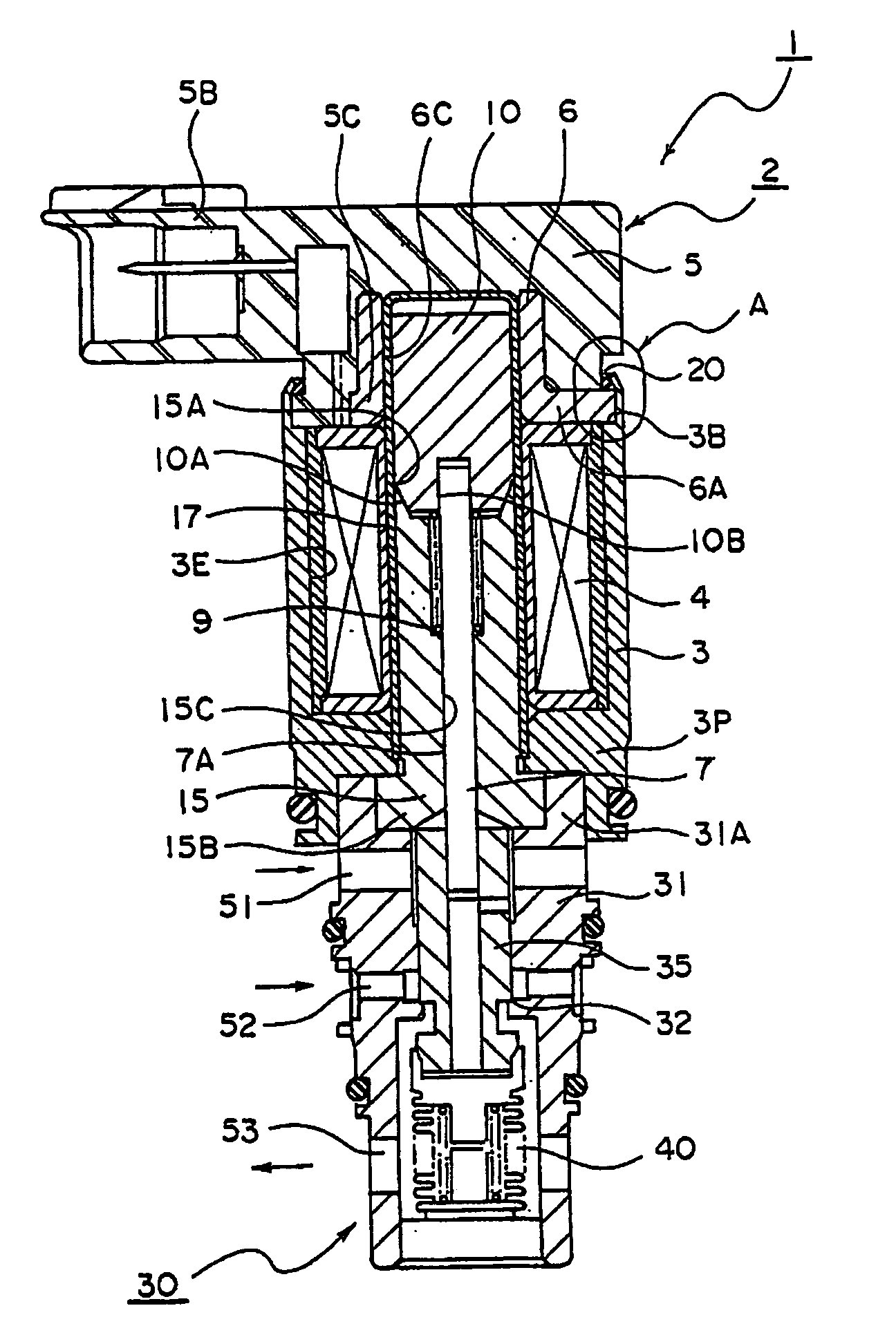
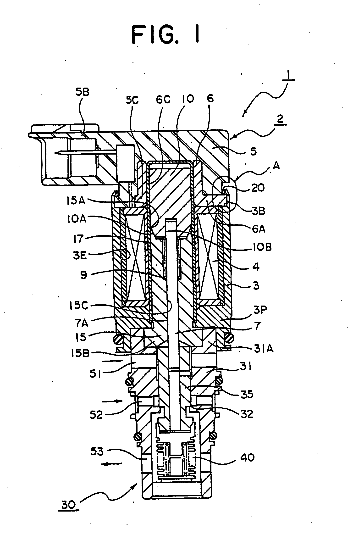
[0025]FIG. 1 is a cross sectional view of a solenoid control valve showing a preferred embodiment relative to the present invention. Reference numeral 1 in FIG. 1 signifies a solenoid control valve. The solenoid control valve 1 is so constructed that a solenoid portion 2 is connected with a valve portion 30. The valve portion 30 disposes a valve housing 31 which defines the outer shape of the valve portion. The valve housing 31 forms a through hole therewithin. And the valve housing 31 is made of metal such as brass, aluminum, stainless or the like, synthetic resin, or the like.

[0026]The valve housing 31 has a valve chamber in a large diameter which is located above the through hole in the figure. There is disposed a connecting p...


PUM


Abstract

A case main body and an upper plate are reliably fitted together, a seal is formed between the fitting surfaces, and a magnetic circuit is prevented from malfunctioning. A solenoid-controlled valve, which connects a solenoid section (2) and a valve section (30), comprises a cylindrical case main body (3) having a solenoid coil (4) housed therein and having a connecting section (3A) at one end, an upper plate (6) having a locking surface (6B) adapted to be fitted to the connecting section (3A), and a connector (5) integrally provided with the upper plate (6). A seal section (20) is joined to an outer surface between the fitting surfaces of the connecting section (3A) and the upper plate (6).

Description

TECHNICAL FIELD[0001]The present invention relates to a solenoid control valve. More particularly, the invention relates to a solenoid control valve which enhances performance of the solenoid portion and reduces the assembly cost by improving a connecting structure of the casing main body and the upper plate.BACKGROUND ART[0002]The present invention relates to an improvement technology over solenoid control valves as prior art. The solenoid control valve as a first prior art is shown in FIG. 3. FIG. 3 represents a relative art of the present invention which is used as a solenoid control valve for a compressor or the like.[0003]In FIG. 3, a valve portion 130 given in the lower part of the figure and a solenoid portion 101 are connected with each other by fitting the outer diameter surface on the upper side of a casing main body 103 to a mount borehole, which is located at the lower end of the casing main body 103 of the solenoid portion 101. And the solenoid portion 101 is assembled ...

Claims


Application Information

Patent Timeline
IPC IPC(8): F16K31/02
CPCF04B27/1804F04B2027/1827F16K31/0668F04B2027/1854F16K31/0613F04B2027/1831
Inventor IWA, TOSHIAKISASAKI, SHINJIHIRATA, ICHIROUEMURA, NORIO
Owner EAGLE INDS
Why Eureka
Try Eureka