
Advanced cooling method for combustion turbine airfoil fillets

a technology of combustion turbines and airfoils, which is applied in the direction of liquid fuel engines, vessel construction, marine propulsion, etc., can solve the problems of turbine airfoils, turbine airfoils, and localized hot spots forming,

Inactive Publication Date: 2008-07-10
SIEMENS ENERGY INC
View PDF27 Cites 41 Cited by
  • Summary
  • Abstract
  • Description
  • Claims
  • Application Information

AI Technical Summary

Benefits of technology

[0015]An advantage of this invention is that it provides direct convection cooling to the airfoil fillet region without creating areas of concentrated local stress and reducing the useful life of the airfoil. Another advantage of the invention is that it provides a cooling method that delivers impingement cooling, vortex cooling, or both, to the fillet region. Yet another advantage of the invention is that it provides an integrated fillet cooling system that provides both direct convection cooling of the fillet region without reducing the useful life of the airfoil combined with impingement cooling, vortex cooling, or both, to the fillet region.
[0016]These and other embodiments are described in more detail below.

Problems solved by technology

In addition, turbine airfoils often contain cooling systems for prolonging the life of the turbine airfoils and reducing the likelihood of failure as a result of excessive temperatures.
However, localized hot spots may form where parts of the turbine airfoil are not adequately cooled.
These localized hot spots may damage the turbine airfoil and may eventually necessitate replacement of the turbine airfoil.
One area of a turbine airfoil that is particularly difficult to cool is the fillet at the intersection between the generally elongated airfoil and the end wall.
Thus, conventional impingement cooling and convection cooling of the inner surface of the generally elongated airfoil or end plate is less effective for cooling the fillet region.
Second, due to the high local Stresses, convection cooling holes that penetrate the outer surface of the fillet are not desirable because such holes may concentrate the local stresses thereby significantly reducing the useful life of the turbine airfoil.
Finally, film cooling along the outer surface of the fillet generally provides only limited cooling to the fillet because the horseshoe vortex may sweep the film away from the fillet or the film has mixed with hot gases prior to reaching the fillet thereby substantially reducing the film's effectiveness.

Method used


Image

  • Advanced cooling method for combustion turbine airfoil fillets
  • Advanced cooling method for combustion turbine airfoil fillets
  • Advanced cooling method for combustion turbine airfoil fillets

Examples


Embodiment Construction

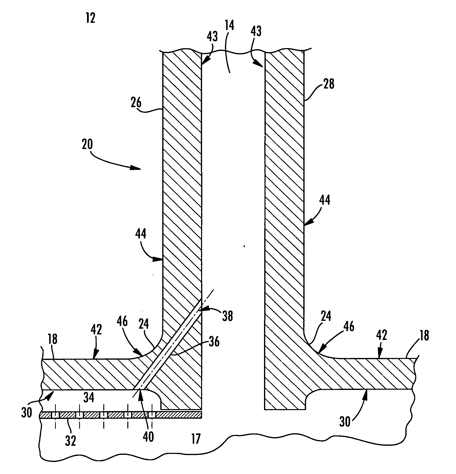
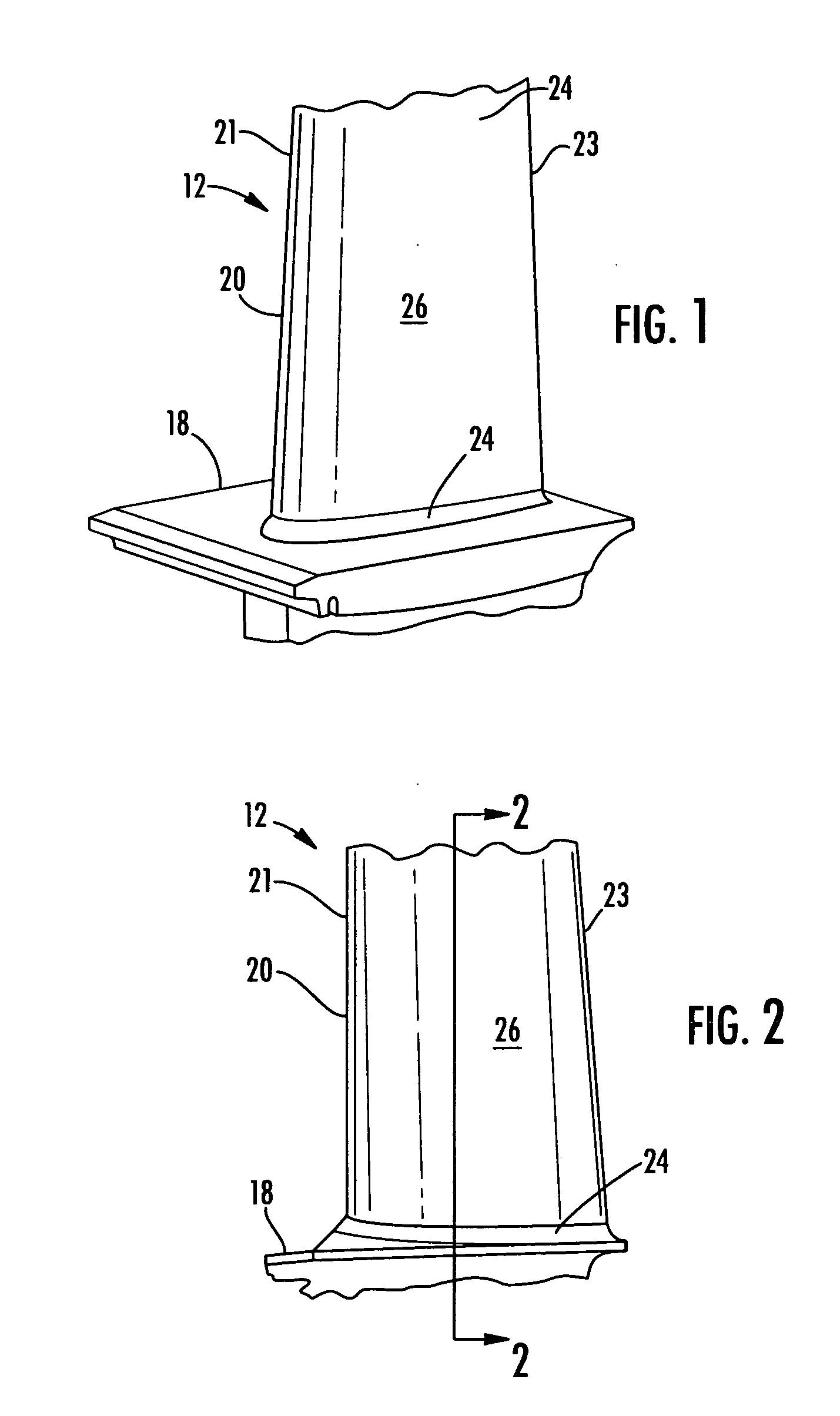
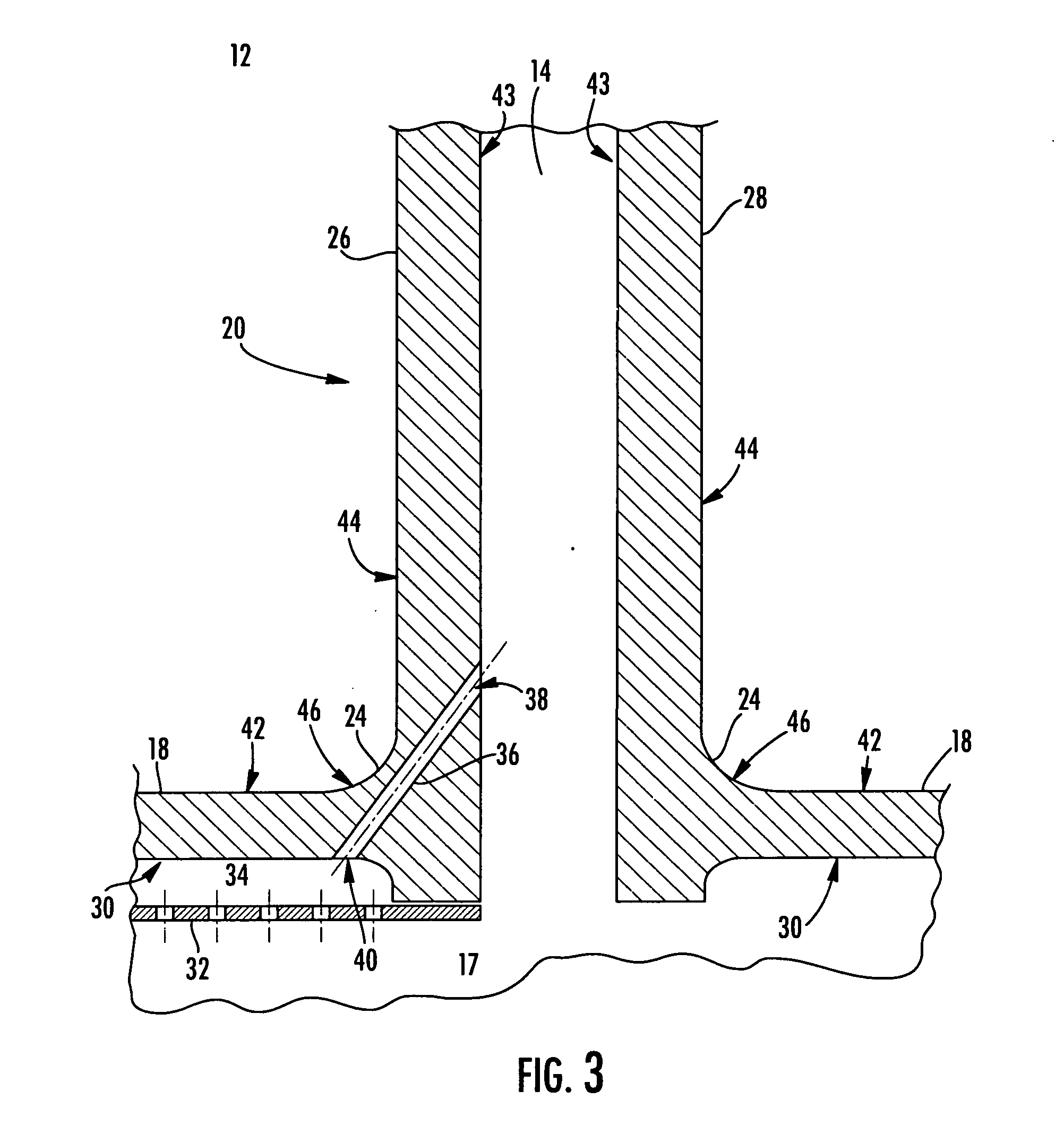
[0030]This invention is directed to a turbine airfoil 12 that includes a fillet cooling system 17 designed to provide direct cooling to the fillet 24. Although the fillet 24 of a turbine vane 12 is used to illustrate the present invention, it should be understood that the invention applies equally to fillets 24 of turbine blades 12. In order to make application of the present invention to blades more apparent, where possible the detailed description uses terminology that may be applied to turbine airfoils 12, whether a blade 12 or a vane 12.

[0031]FIGS. 1 through 12 show the radially inward half of a turbine airfoil 12, a turbine vane 12 in this instance. A turbine airfoil 12 may be formed from a generally elongated airfoil 20 coupled at one end to an end wall 18. The turbine airfoil 12 may have a leading edge 21 and a trailing edge 23. The generally elongated airfoil 20 may be formed from a generally concave shaped portion forming a pressure side wall 26 and may have a generally con...


PUM


Abstract

The present invention is directed to a hollow turbine airfoil having a cooling system designed to provide enhanced cooling to the fillet of a turbine airfoil. The turbine airfoil may include at least one fillet cooling channel, passing proximate to the fillet. A portion of the fillet cooling channel may be positioned proximate to the fillet outer surface without breaching an outer surface of the turbine airfoil. The turbine airfoil may include a vortex plate positioned adjacent to the end wall inner surface proximate to the fillet and an opening of the fillet cooling channel may be in fluid communication with the vortex chamber. The turbine airfoil may also include at least one end wall film cooling channel that may extend obliquely through the end wall and may be in fluid communication with the vortex chamber.

Description

FIELD OF THE INVENTION[0001]The present invention is directed generally to cooling turbine components of gas turbine systems, and more particularly to cooling a fillet between an end wall and an airfoil in a gas turbine blade or vane.BACKGROUND OF THE INVENTION[0002]Typically, gas turbine engines include a compressor for compressing air, a combustor for mixing the compressed air with fuel and igniting the mixture, and a turbine blade assembly for producing power. Combustors often operate at high temperatures that may exceed 2,500 degrees Fahrenheit. Typical turbine combustor configurations expose turbine blade and vane assemblies to these high temperatures. As a result, turbine rotating blades and turbine stationary vanes (hereafter “turbine airfoils”) must be made of materials capable of withstanding such high temperatures. In addition, turbine airfoils often contain cooling systems for prolonging the life of the turbine airfoils and reducing the likelihood of failure as a result o...

Claims


Application Information

Patent Timeline
IPC IPC(8): F01D5/18
CPCF05B2240/801F01D5/187F05D2240/81F05D2260/205F05D2240/126F01D9/065
Inventor SCOTT, ROBERT KENMERBEECK, ALEXANDER RALPH
Owner SIEMENS ENERGY INC
Features
  • Generate Ideas
  • Intellectual Property
  • Life Sciences
  • Materials
  • Tech Scout
  • Unparalleled Data Quality
  • Higher Quality Content
  • 60% Fewer Hallucinations
Learn More