
Method of manufacturing thin film magnetic head

a manufacturing method and magnetic head technology, applied in the field of manufacturing a thin film magnetic head, can solve the problems of greater fluctuation between products and unstable writing characteristics, and achieve the effect of suppressing fluctuation and non-uniformity, and suppressing dulling of the magnetic pole tip portion

Inactive Publication Date: 2008-07-17
FUJITSU LTD
View PDF0 Cites 2 Cited by
  • Summary
  • Abstract
  • Description
  • Claims
  • Application Information

AI Technical Summary

Benefits of technology

[0029]If the divergence angle of the ion beam used during ion milling is reduced to around 3°, for example, the dulling of the magnetic pole tip portion can be reduced and the magnetic pole tip portion can be formed with a substantially equal width from the boundary with the yoke portion to the float surface.
[0030]However, the present inventor has found a problem with a write magnetic pole formed using an ion beam with a small divergence angle in that as shown in FIG. 8 (a cross-sectional view where the write magnetic pole 100 is viewed from the float surface side), concaves and convexes are formed in the upper magnetic layer 19 and the surface of the lower magnetic pole layer 10, which means increased fluctuation in the write core width of the write magnetic pole 100 and leads to greater fluctuation in the write characteristics.
[0032]The present invention was conceived to solve the problem described above and it is an object of the present invention to provide a method of manufacturing a thin film magnetic head that can suppress dulling of the magnetic pole tip portion of the write magnetic pole during ion milling carried out when forming the write magnetic pole and can also suppress fluctuation and non-uniformity in the write core width of the write magnetic pole.
[0034]By carrying out extensive research into a method that can smooth out such concaves and convexes due to the shape of the crystal grain boundaries to smoothly form the surface of the magnetic pole and can also form the magnetic pole tip portion sharply without dulling, the present inventor completed the present invention.
[0038]By doing so, concaves and convexes due to the shape of the crystal grain boundaries can be smoothed out by the ion beam with the wider divergence angle and the magnetic pole tip portion can be sharply formed without dulling by the ion beam with the narrower divergence angle.
[0041]With the method of manufacturing a thin film magnetic head according to the present invention, it is possible to suppress dulling of a magnetic pole tip portion of a write magnetic pole during ion milling carried out when forming the write magnetic pole and to also suppress fluctuation and nonuniformity in the write core width of the write magnetic pole.

Problems solved by technology

As a result, there are problems such as the write characteristics becoming unstable and greater fluctuation between products.

Method used


Image

  • Method of manufacturing thin film magnetic head
  • Method of manufacturing thin film magnetic head
  • Method of manufacturing thin film magnetic head

Examples


Embodiment Construction

[0050]A preferred embodiment of a method of manufacturing a thin film magnetic head according to the present invention will now be described.

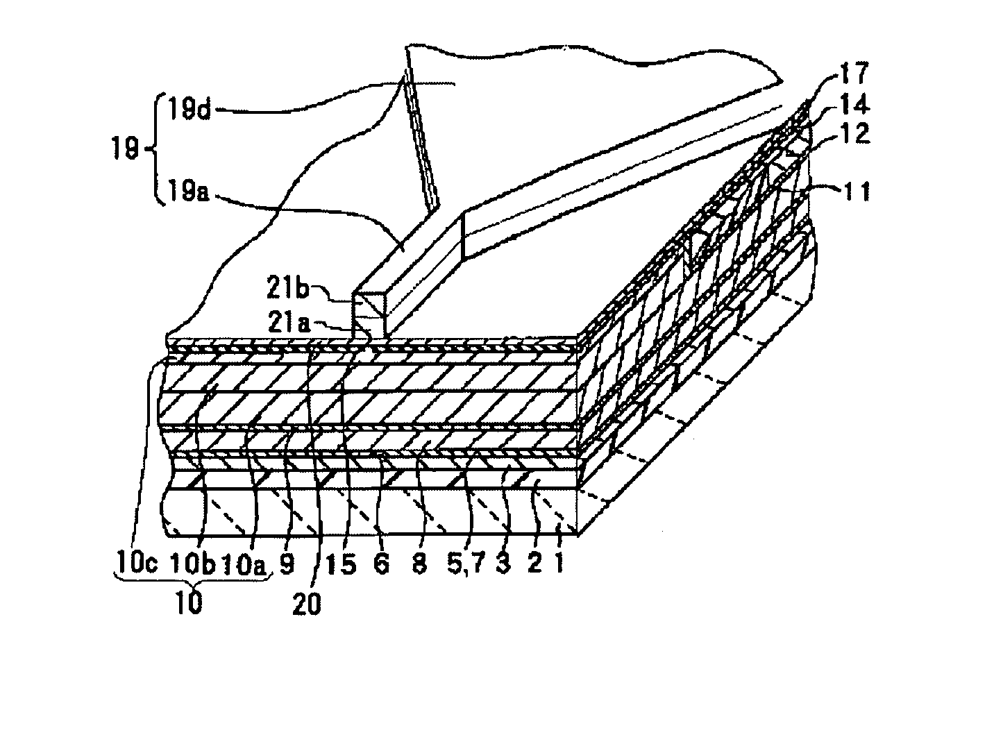
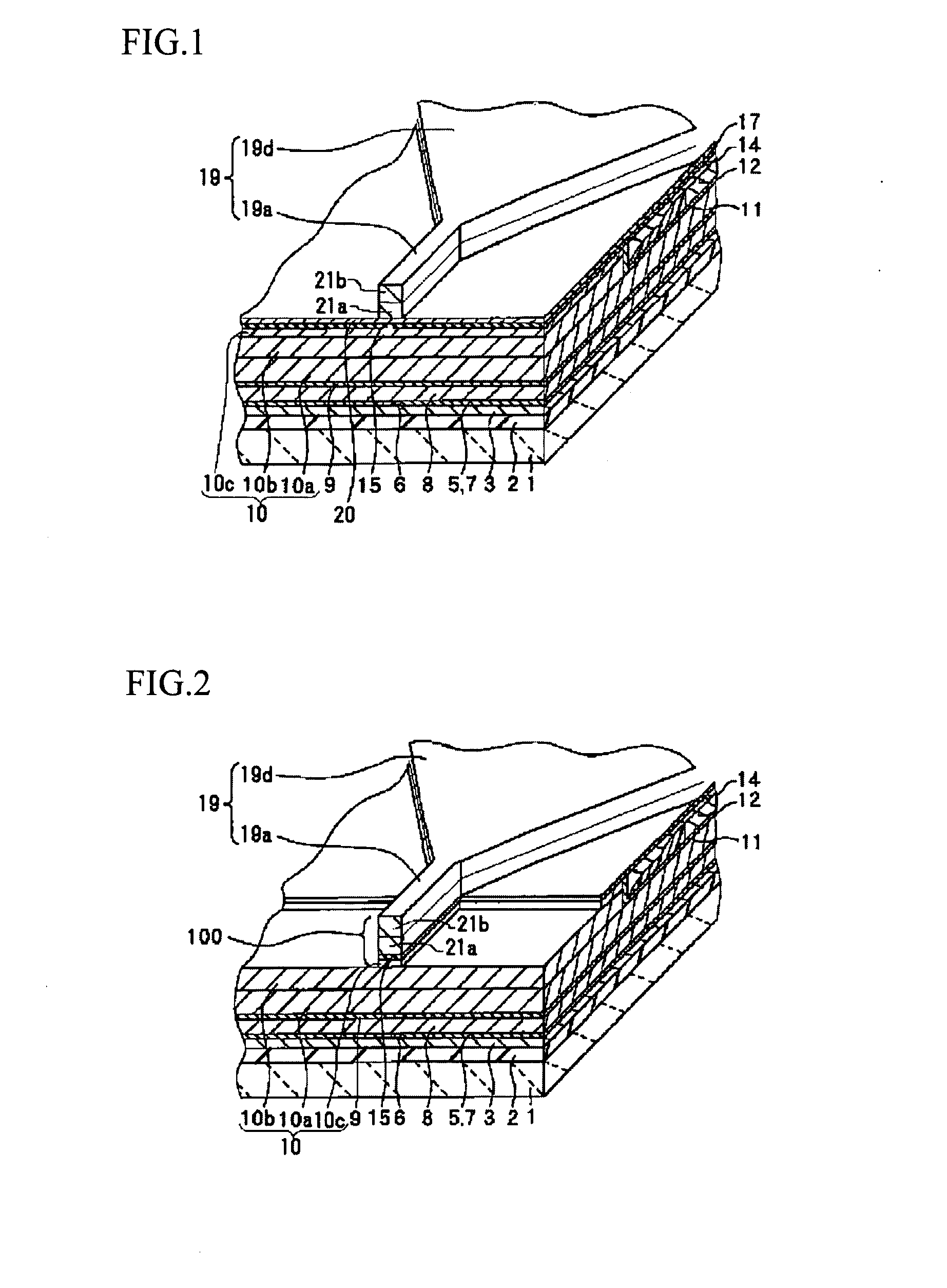
[0051]FIGS. 1 and 2 are schematic diagrams showing a thin film magnetic head manufactured by a method of manufacturing a thin film magnetic head according to the present embodiment. Note that in FIGS. 1 and 2, the cross section shown in the near side of the drawings is the float surface when the thin film magnetic head is completed.

[0052]In the method of manufacturing a thin film magnetic head according to the present embodiment, since the process that forms the reproduction head is the same as that described above in the “Related Art” section, detailed description thereof is omitted. Therefore, the method of forming the layers above the lower magnetic pole layer 10 that compose the recording head will be described below with reference to FIGS. 1 and 2.

[0053]Note that in FIGS. 1 and 2, members that are the same as the thin film magnetic heads s...


PUM

PropertyMeasurementUnit
Angleaaaaaaaaaa
Angleaaaaaaaaaa
Electrical conductoraaaaaaaaaa

Abstract

A method of manufacturing a thin film magnetic head can suppress dulling of a magnetic pole tip portion of a write magnetic pole during ion milling carried out when forming the write magnetic pole, and can also suppress fluctuation and nonuniformity in the write core width of the write magnetic pole. The method includes a laminating process of successively laminating a lower magnetic pole layer, a gap layer on the lower magnetic pole layer, and an upper magnetic pole layer on the gap layer to produce a laminated film and an ion milling process of irradiating the laminated film produced by successively laminating the lower magnetic pole layer, the gap layer, and the upper magnetic pole layer from above with an ion beam to trim the laminated film to a narrow width and thereby form the lower magnetic pole layer, the gap layer, and the upper magnetic pole layer into a write magnetic pole. During the ion milling process, trimming is carried out using an ion beam with a first divergence angle and then trimming is carried out using an ion beam with a second divergence angle that differs to the first divergence angle.

Description

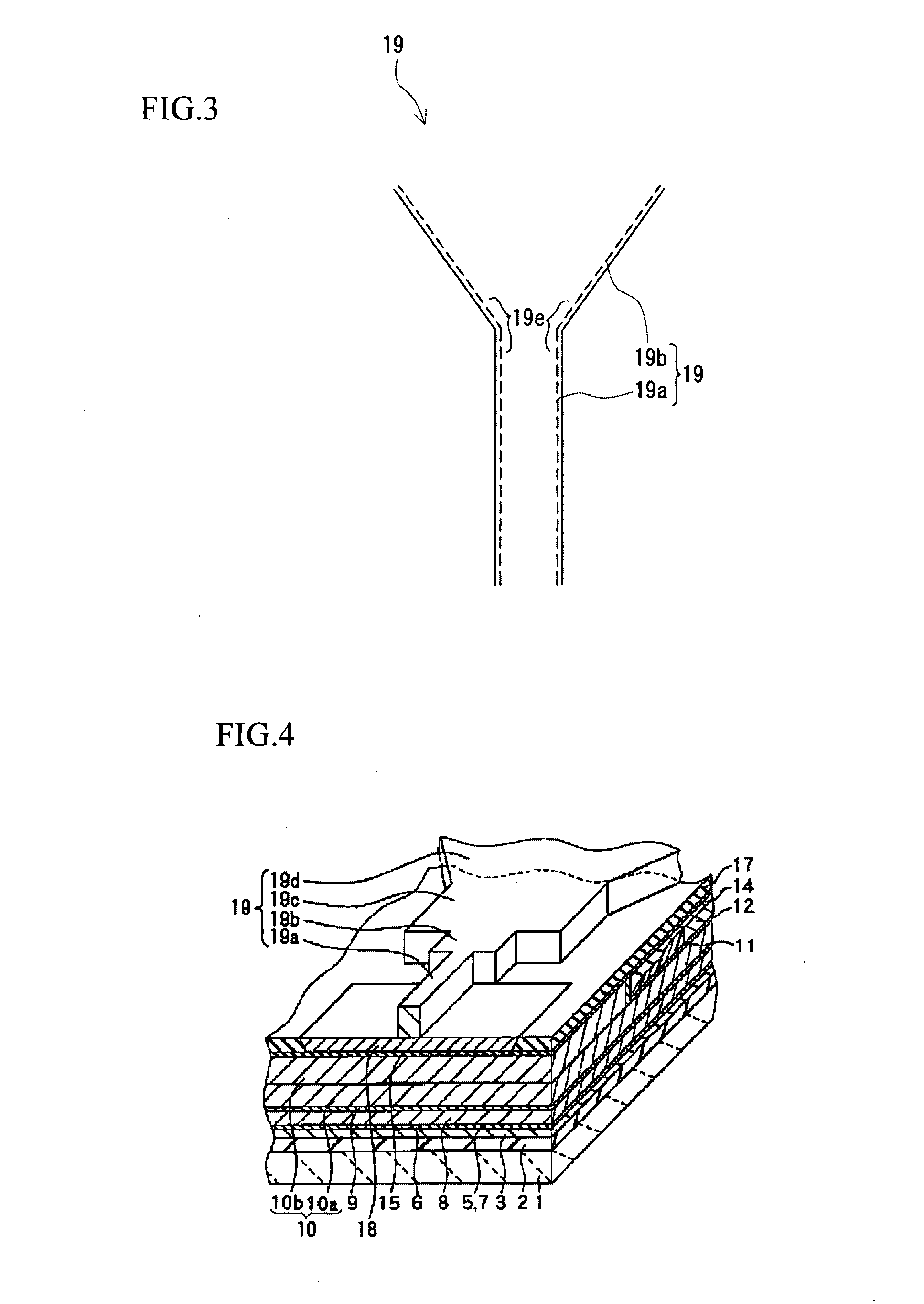
BACKGROUND OF THE INVENTION[0001]1. Field of the Invention[0002]The present invention relates to a method of manufacturing a thin film magnetic head including an ion milling process that irradiates a laminated film, which has been produced by successively laminating a lower magnetic pole layer, a gap layer, and an upper magnetic pole layer in that order, with an ion beam to trim the laminated film into a narrow width and thereby form the lower magnetic pole layer, the gap layer, and the upper magnetic pole layer into a write magnetic pole.[0003]2. Related Art[0004]A conventional method of manufacturing a thin film magnetic head is disclosed in Patent Document 1. FIGS. 4 and 5 are schematic diagrams showing a thin film magnetic head manufactured by this conventional method of manufacturing a thin film magnetic head. Note that in FIGS. 4 and 5, the cross section shown in the nearside of the diagrams is the float surface when the thin film magnetic head is completed.[0005]In the conven...

Claims


Application Information

Patent Timeline
IPC IPC(8): C25D5/00C23C14/32
CPCB82Y25/00B82Y40/00H01F41/308G11B5/3116G11B5/3163C25D5/10C25D5/12G11B5/31G11B5/127
Inventor DAIMATSU, HIDEAKIITO, TAKASHI
Owner FUJITSU LTD
Learn More