Display device

a display device and display technology, applied in the field of display devices, can solve the problems of increasing manufacturing costs, increasing manufacturing costs, and complicated device structure, and achieve the effects of uniform and efficient cooling, low manufacturing cost, and low manufacturing cos

Active Publication Date: 2008-07-17
MITSUBISHI ELECTRIC CORP
View PDF7 Cites 19 Cited by
  • Summary
  • Abstract
  • Description
  • Claims
  • Application Information

AI Technical Summary

Benefits of technology

[0010]According to the display device disclosed in the above patent document 1, as described above, the cooling ability for the substrate can be improved to some extent actually, by providing the ventilation hole so as to penetrate the display unit from its front to back and flowing the wind. However, in this case, it is necessary to provide the ventilation hole in the display unit, thereby the manufacturing cost is increased and the structure of the device becomes complicated. In addition, since a mold material surrounding the substrate and the ventilation hole serves as thermal resistance, the cooling efficiency is lowered for that. Furthermore, it is necessary to take measures to drain rainwater and the like that could enter the ventilation holes, which causes the manufacturing cost to be further increased and the structure to become more complicated.
[0012]The present invention was made in view of the above technical problems and it is a basic object of the present invention to cool down a substrate on which the light emitting elements are arranged uniformly and efficiently in a display device using light emitting elements without causing its cost to be excessively increased or its structure to become excessively complicated.
[0014]According to the present invention, the wind path plate forming the wind path to pass the airflow generated by driving the fan unit is provided between the back surface of the substrate having the light emitting elements for display on the front surface and the fan unit, and the airflow generated by driving the fan unit impinges the wind path plate through the fan, thereafter passes through the wind path and is discharged to the outside from the back side of the wind path plate. Therefore, the substrate can be uniformly cooled down all over the whole surface from its back surface by the airflow passing through the wind path. Thus, since the light emitting elements on the substrate can be cooled down uniformly and efficiently, an even-colored and high-reliability display device can be obtained. In this case, since the structure can be provided by a relatively simple way such as by providing the wind path plate between the back surface of the substrate and the fan unit, the structure is not complicated and the cost is not high like the conventional case.

Problems solved by technology

However, in this case, it is necessary to provide the ventilation hole in the display unit, thereby the manufacturing cost is increased and the structure of the device becomes complicated.
Furthermore, it is necessary to take measures to drain rainwater and the like that could enter the ventilation holes, which causes the manufacturing cost to be further increased and the structure to become more complicated.
However, its maintenance function or assembling performance to a module deteriorates as compared with the case the power supply is incorporated in each unit.

Method used


Image

  • Display device
  • Display device
  • Display device

Examples


first embodiment

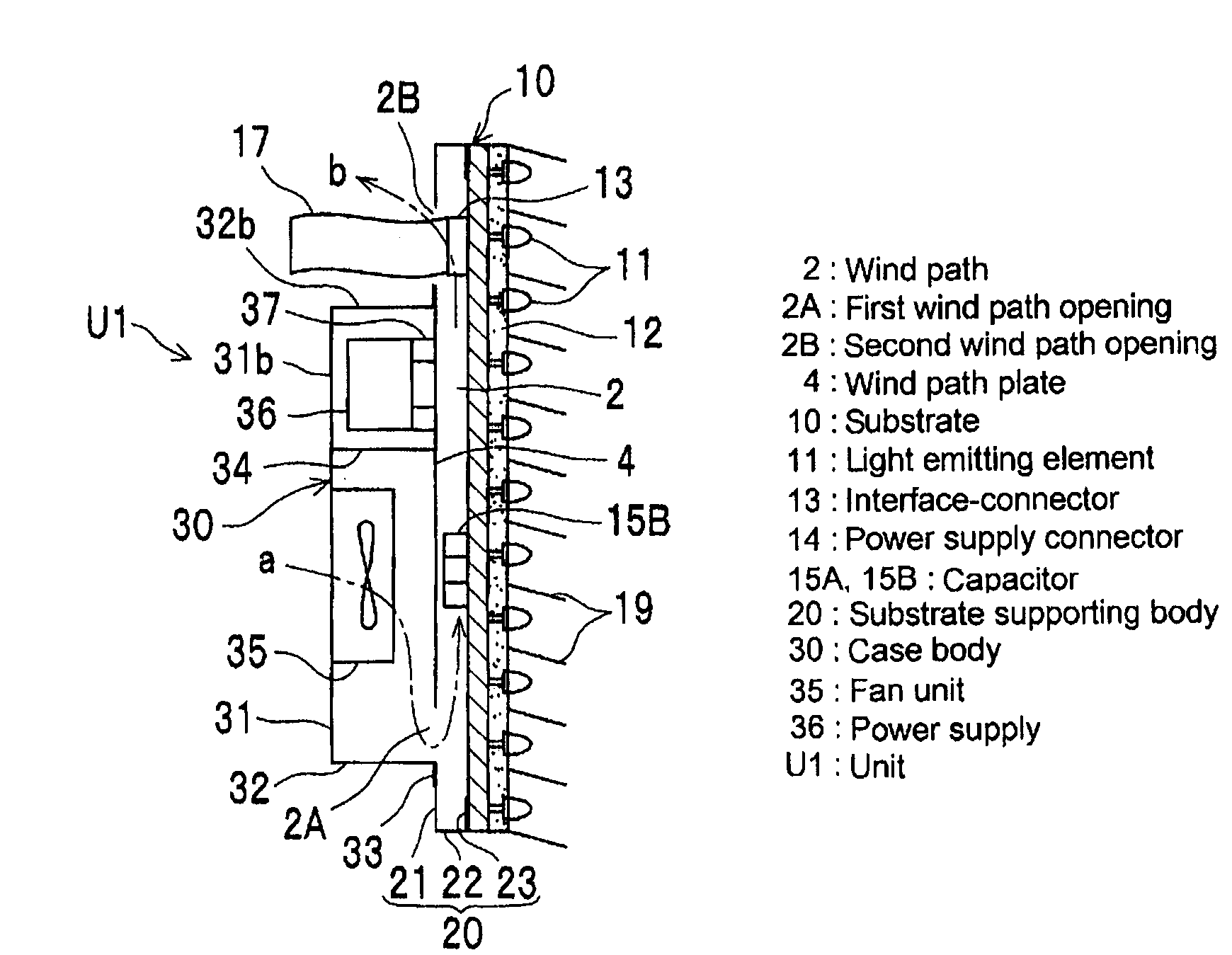
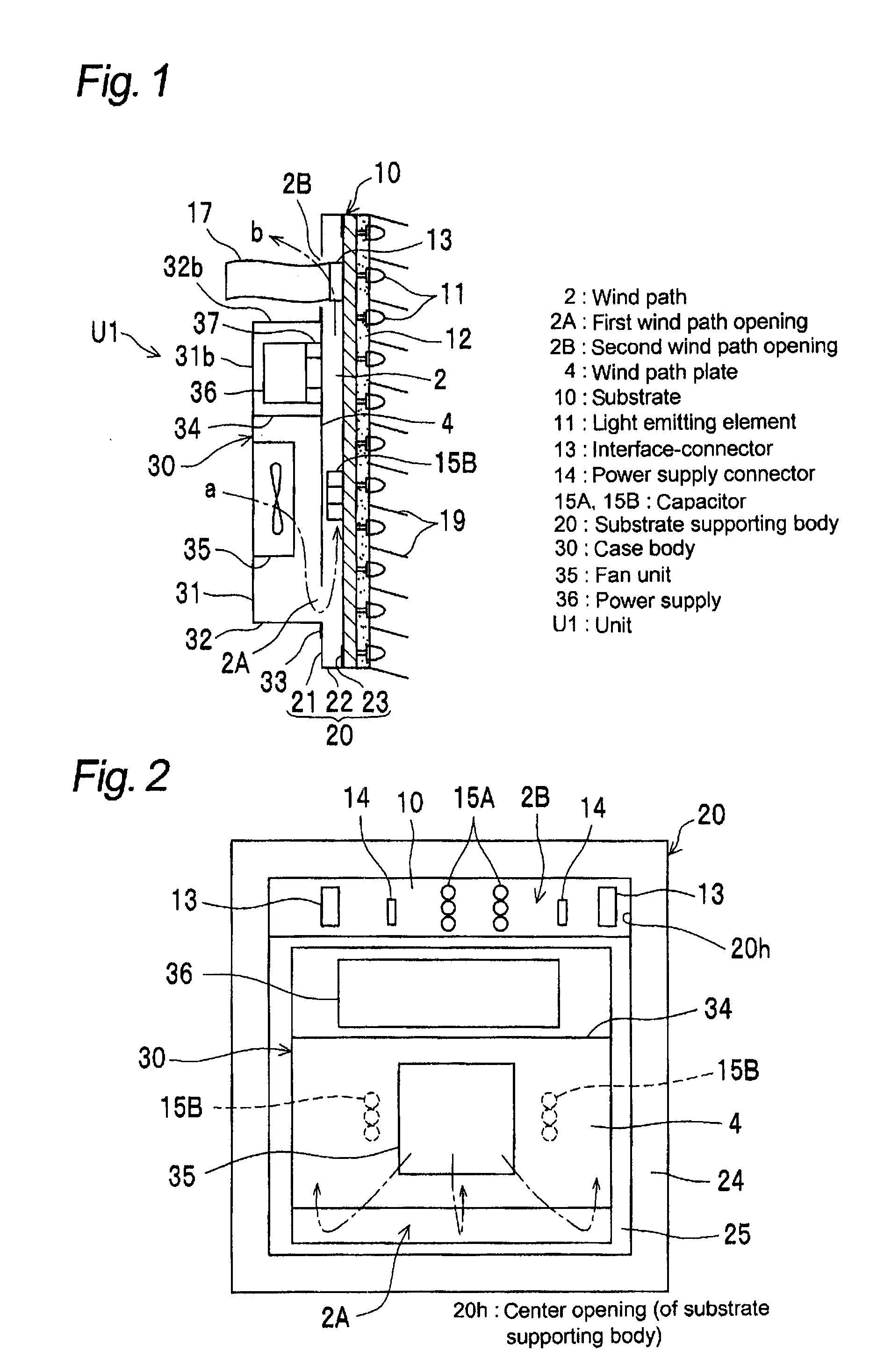
[0023]FIG. 1 is a schematic sectional view showing a sectional structure of a single unit of a display device according to a first embodiment of the present invention, and FIG. 2 is a schematic back view showing a back surface structure of the single unit.

[0024]As shown in the above views, a (single) unit U1 of the display device according to the first embodiment includes a rectangular substrate 10 on which light emitting elements 11 for display are arranged on a front surface (right surface in FIG. 1), and a rectangular substrate supporting body 20 positioned on the back surface deft surface in FIG. 1) side of the substrate 10 to support a peripheral region of the substrate 10.

[0025]The substrate supporting body 20 has a rectangular opening 20h (center opening) in the center and it is in the shape of a frame in planar view, and its peripheral part supports the back surface of the peripheral region of the substrate 10.

[0026]More specifically, the substrate supporting body 20 has a k...

second embodiment

[0071]Next, a second embodiment of the present invention will be described.

[0072]In the following explanation, elements of the second embodiment having substantially same structures and substantially same effects as those of the first embodiment will be designated with the same symbols and further explanation thereof will be omitted.

[0073]FIG. 6 is a back view schematically showing a back structure of a single unit of a display device according to the second embodiment of the present invention, which corresponds to FIG. 2 in the first embodiment.

[0074]As shown in this drawing, in a (single) unit U2 of the display device according to the second embodiment, as similar to the case in the first embodiment, a second wind path opening 2B to flow air in or out of the wind path 2 is provided between an opening edge of a center opening 20h of a substrate supporting body 20 and one end of a wind path plate 4. In addition, in a case body 30, a power supply 36 is arranged closer to the second w...

third embodiment

[0081]Next, a third embodiment of the present invention will be described.

[0082]FIG. 7 is a partially enlarged sectional view schematically showing a part of a sectional structure of a single unit of a display device according to the third embodiment.

[0083]As shown in FIG. 7, according to a (single) unit U3 of the display device in the third embodiment, a substrate supporting body 40 has a U-shaped sectional structure consisting of a back plate 41, a side plate 42 extending from the peripheral part of the back plate 41 to the front, and a receiver part 43 provided by folding the front end of the side plate 42. And the receiver part 43 is provided with a screw hole 43b for a screw to fix a substrate 10 on the front surface side of the receiver part 43.

[0084]In this case, a flange part 53 of a case body 50 is fixed to the back plate 41 of the substrate supporting body 40 with a screw, on the end portion of the unit shown in FIG. 7.

[0085]In this embodiment, the distance between the rec...


PUM


Abstract

A display device includes a substrate having light emitting elements for display on a front surface; a substrate supporting body having an opening in the center and positioned on the back surface side of the substrate to support a peripheral region of the substrate; a case body positioned on the back surface side of the substrate supporting body and covering a part of the center opening; a fan unit arranged in the case body; a wind path plate arranged between the fan unit and the back surface of the substrate and forming a wind path to pass airflow generated by driving the fan unit only on the back surface side of the substrate; and a power supply arranged in the case body and on the back surface of the wind path plate; and wherein the airflow impinges the wind path plate through the fan, thereafter passes through the wind path and is discharged to the outside from the back side of the wind path plate. According to the present invention, it is possible to cool down a substrate uniformly and efficiently in a display device using light emitting elements arranged on the substrate without raising cost or complicating the structure.

Description

BACKGROUND OF THE INVENTION[0001]1. Field of the Invention[0002]The present invention relates to a display device including light emitting elements for display and more particularly, to a display device including a fan unit capable of preventing a temperature elevation due to heat generated by the emission of the light emitting elements.[0003]2. Description of the Related Art[0004]Recently, a display device using a plasma display, a liquid crystal display, a field emission display, a light emitting diode (hereinafter, referred to as the LED appropriately) or the like is widely known in general in a field of the display device, and it is increasingly employed together with a conventional display device using a CRT (Cathode Ray Tube) or a discharge tube, or instead of this.[0005]However, according to the above display device, since its light conversion efficiency is low and it is about 10% in the case of the LED element, it means that a most part of supply power is converted to heat. ...

Claims


Application Information

Patent Timeline
Patent Type & Authority Applications(United States)
IPC IPC(8): G09G3/32
CPCG02F2001/133628G02F1/133603G02F1/133628
Inventor KISE, KOJIIOKI, KAZUHIROIWASAKI, YOSHIMIKAWAGUCHI, HIRONOBU
Owner MITSUBISHI ELECTRIC CORP
Why Eureka
Try Eureka