

Fuel cell
- Summary
- Abstract
- Description
- Claims
- Application Information
AI Technical Summary
Benefits of technology
Problems solved by technology
Method used
Image

Examples
first embodiment
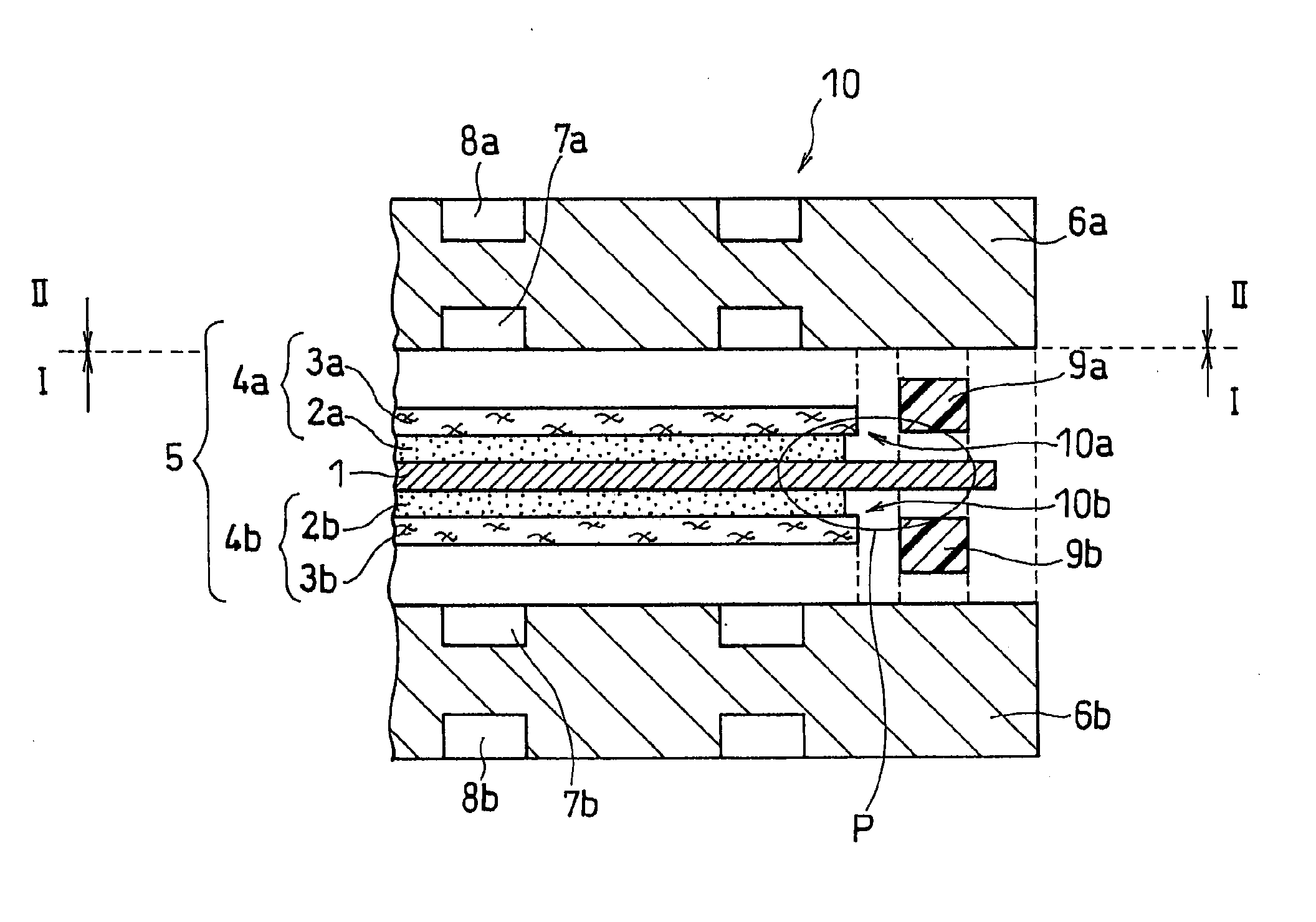
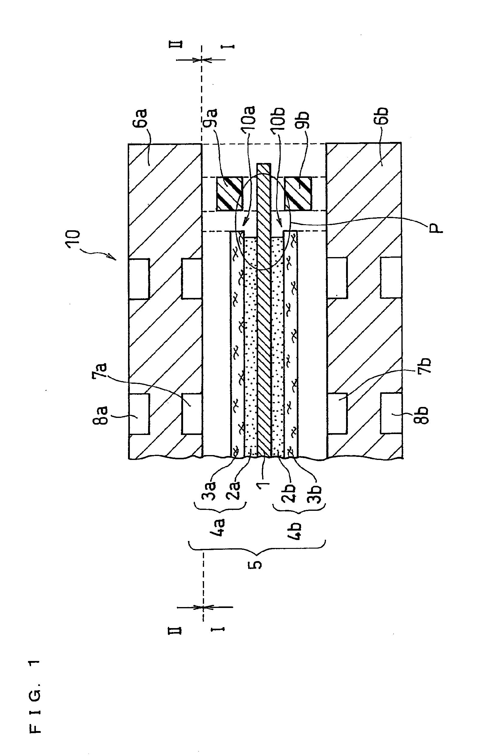
[0049]FIG. 1 is a schematic exploded sectional view showing a main part of a basic configuration of a first embodiment of a polymer electrolyte fuel cell of the present invention. A fuel cell 10 of the present invention, configured by combining the components as shown in FIG. 1 in the positions as shown by broken line, comprises at least one unit cell mainly including a membrane electrode assembly (MEA) 5, and a pair of plate-shaped separators sandwiching the membrane electrode assembly 5, namely, an anode-side separator 6a and a cathode-side separator 6b.
[0050]The membrane electrode assembly 5 has a configuration such that a polymer electrolyte membrane (e.g., Nafion 112 (trade name) membrane made of perfluorocarbon sulfonic acid available from E.I. du Pont de Nemours and Company, U.S.A.) 1 for selectively transporting cations (hydrogen ions) is disposed between an anode 4a and a cathode 4b. Further, the anode 4a at least includes a catalyst layer 2a disposed in its polymer electr...
second embodiment
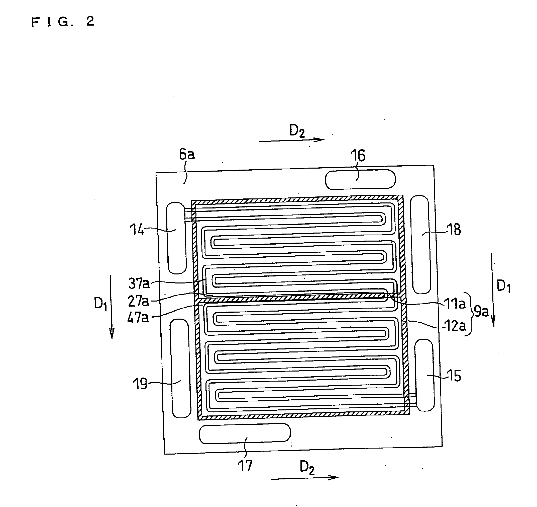
[0085]Next, a second embodiment of the fuel cell of the present invention is described. A fuel cell (not shown) of this second embodiment is a variation of the fuel cell 10 of the first embodiment as shown in FIG. 1, in which the configuration of the anode 4a, the cathode 4b and the extra sealing portion 11a is modified. The components other than the anode 4a, the cathode 4b and the extra sealing portion 11a are configured in the same manner as in the fuel cell 10 of the first embodiment. The following is a description of the anode 4a, the cathode 4b and the extra sealing portion 11a included in the fuel cell of the second embodiment.
[0086]FIG. 6 corresponds to FIG. 3 in the first embodiment, showing a cross sectional view taken along line II-II of FIG. 1 (i.e., a front view of the fuel cell 10 of FIG. 1 after the anode-side separator 6a is removed, viewed from its anode-side separator 6a side (before removal)). Although not shown, a front view of the fuel cell 10 after the cathode-...
third embodiment
[0092]Next, a third embodiment of the fuel cell of the present invention is described. A fuel cell (not shown) of this third embodiment is a variation of the fuel cell 10 of the first embodiment as shown in FIG. 1, in which the configuration of the extra sealing portion 11a is modified. The components other than the extra sealing portion 11a are configured in the same manner as in the fuel cell 10 of the first embodiment. The following is a description of the extra sealing portion 11a included in the fuel cell of the third embodiment.
[0093]FIG. 8 corresponds to FIG. 2 in the first embodiment, showing a cross sectional view taken along line I-I of FIG. 1 in the third embodiment (i.e., a front view of the anode-side separator 6a in the fuel cell 10 of this embodiment viewed from its fuel gas flow channel 7a side), a region of which being in contact with the anode-side gasket 9a is shown by hatching. Although not shown, a front view of the cathode-side separator 6b in the fuel cell 10 ...
PUM
 Abstract
Description
Claims
Application Information