Molded plastic and metal combination cutting blade

a technology of molded plastic and cutting blades, which is applied in the field of cutting blades, can solve the problems of large vibration and noise emitted by rotary knives, damage to eardrums, and impair hearing, and achieve the effects of reducing noise and vibration emission, easy molded into the desired configuration, and long li

Inactive Publication Date: 2008-07-24
LONG JOHN W +1
View PDF16 Cites 7 Cited by
  • Summary
  • Abstract
  • Description
  • Claims
  • Application Information

AI Technical Summary

Benefits of technology

[0015]The present invention as thus described has many advantages over those devices found in the prior art. The metal-on-plastic (and vice versa) frictional engagement between the blade support channel and the blade holding ring provides the dual advantage of long lifespan and a significant reduction in noise and vibration emission from the rotary knife. Furthermore, the construction materials used in connection with the present invention are relatively inexpensive and can easily be molded into the desired configurations, and can be done so t...

Problems solved by technology

It has been found that these types of blades are very efficient at removing tissue from the carcass, but there are inherent problems with the use of these knives that have not been solved by the prior art.
One of these problems in the meat packing industry is the large amount of vibration and noise emitted by the rotary knives.
As a result, the metal-on-metal contact of the knife components operating at high-speeds would cause a high-pitched noise that could damage the eardrum and impair hearing.
Additionally, the lack of a damper in the drive mechanism and high-speed operation causes severe vibration of the knife that could result in loss of control of the knife and injury to the user.
While it is possible to reduce vibrations through the use of such a damping device, this does not completely solve the problem.
Als...

Method used


Image

  • Molded plastic and metal combination cutting blade
  • Molded plastic and metal combination cutting blade
  • Molded plastic and metal combination cutting blade

Examples


Embodiment Construction

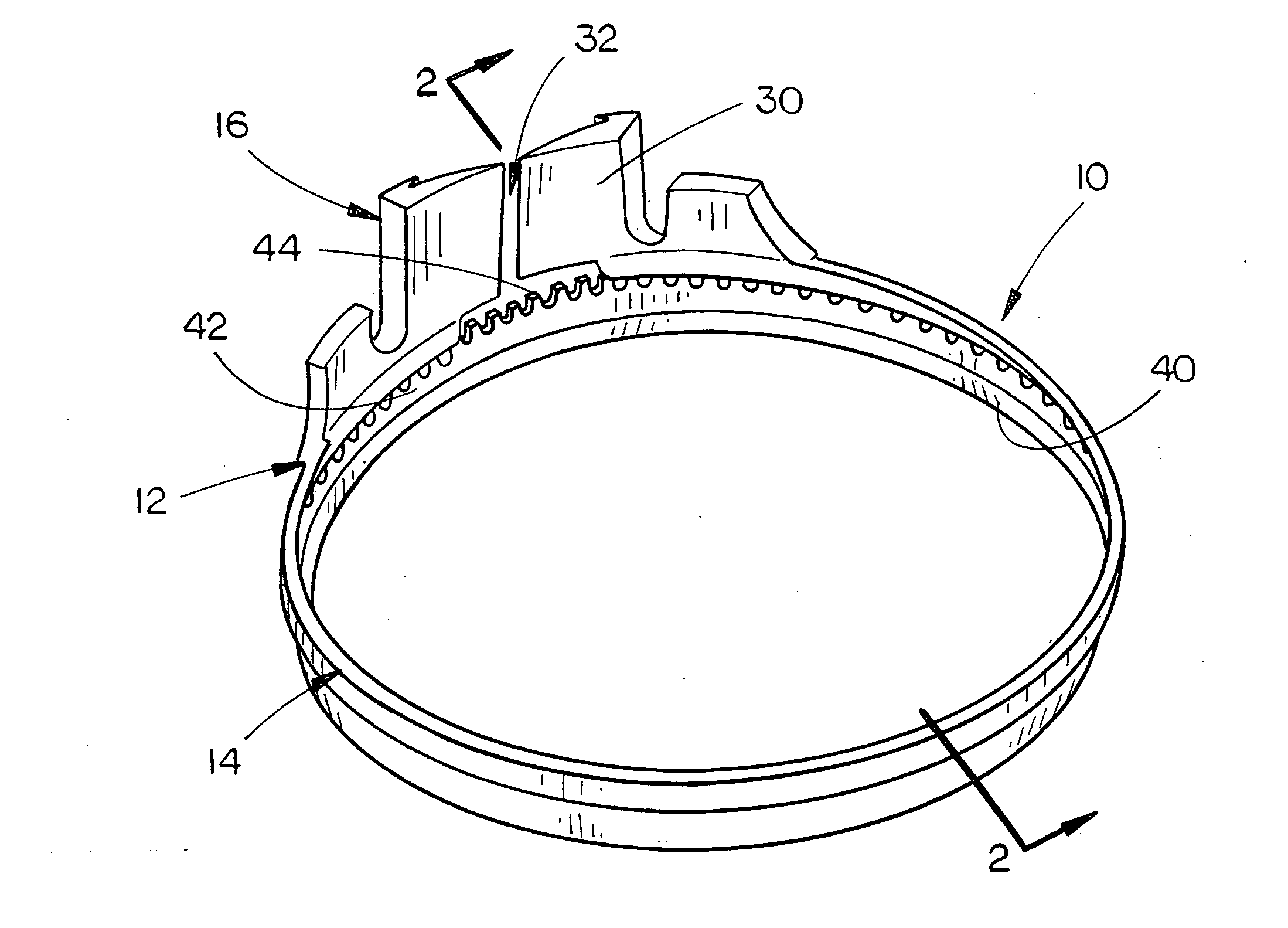
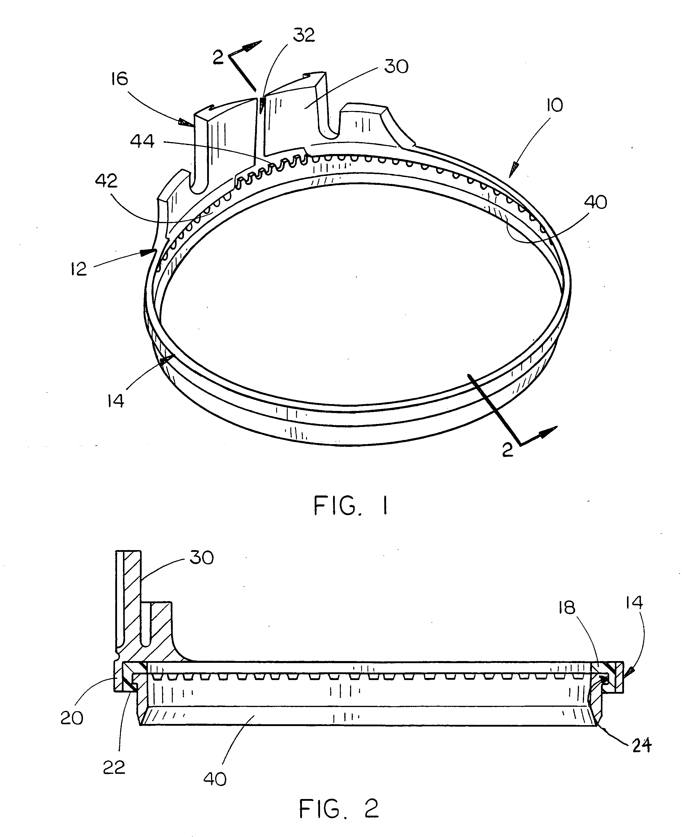
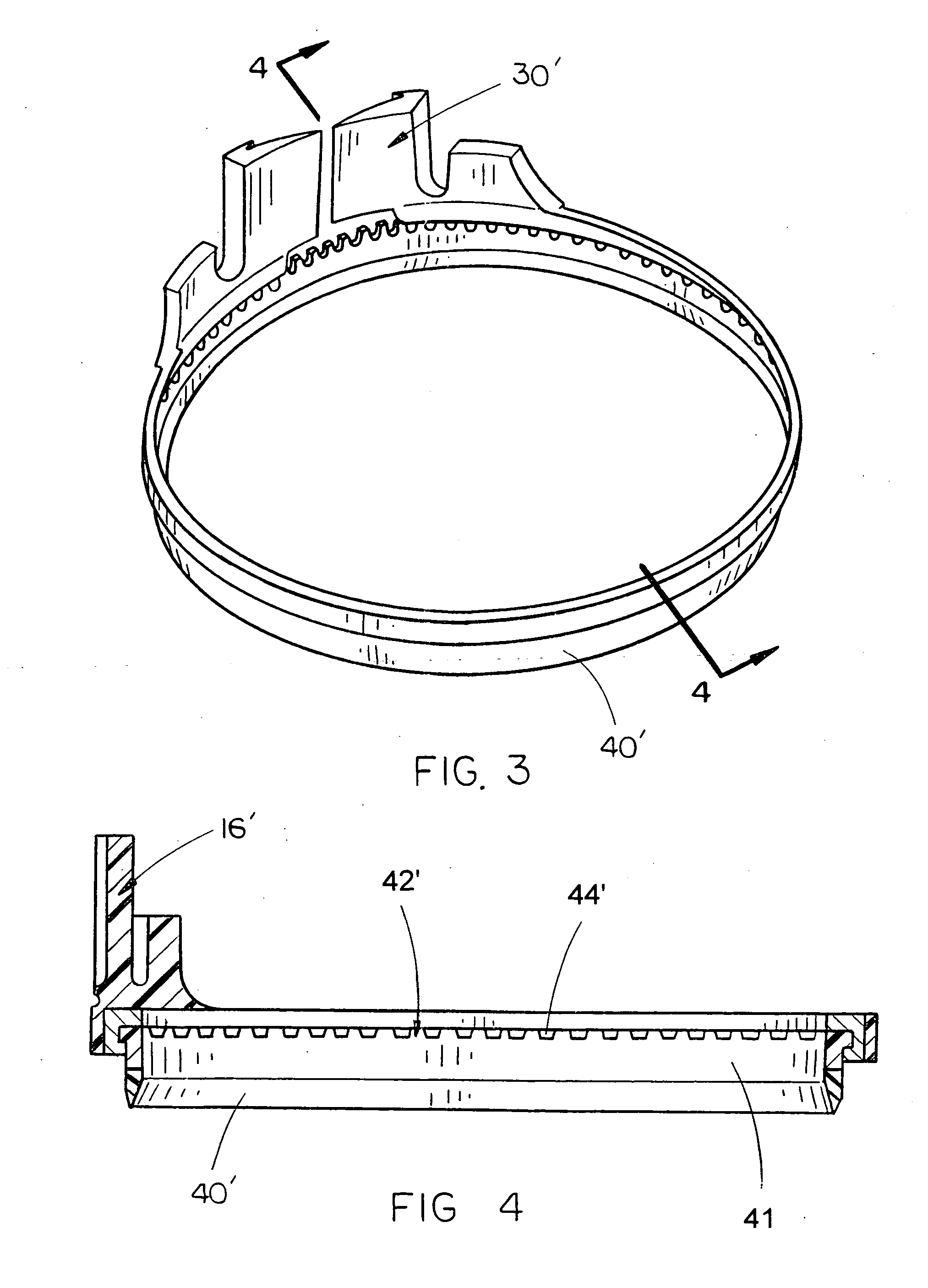
[0020]The molded plastic and metal combination cutting blade 10 of the present invention is shown best in FIGS. 1-4 as including a generally toroidal molded plastic blade support structure 12 which includes a lower blade-engaging ring 14 and an upper mounting section 16. In the preferred embodiment, the lower blade-engaging ring 14 would be constructed to include a top lip 18, sidewall 20 and lower lip 22 which together cooperate to form a blade support channel 24, as shown best in FIG. 2. It is preferred that the blade-engaging ring 14 have a diameter of approximately three to five inches and that the blade support channel 24 have dimensions which approximate the dimensions of the upper part of the blade 40 such that the upper portion 42 of blade 40 is releasably secured within the blade support channel 24 whereby the blade-engaging ring 14 releasably secures and supports the blade 40 therein with the blade 40 being rotatable within the blade support channel 24 of blade-engaging ri...


PUM


Abstract

A blade support structure for a rotary knife blade includes a lower blade-engaging ring and an upper mounting section, the lower blade-engaging ring including a circumferential blade support channel operative to releasably rotatably secure and support a toroidal rotary knife therein. The blade support channel is constructed of material selected from the group consisting of plastic, polyvinyl chloride, polyethylene, polypropylene, polystyrene, vinyl, and polyethylene terephthalate when the upper blade holder engagement section of the toroidal rotary knife is constructed of metal, and the blade support channel is constructed of metal when the upper blade holder engagement section of a toroidal rotary knife is constructed of material selected from the group consisting of plastic, polyvinyl chloride, polyethylene, polypropylene, polystyrene, vinyl, and polyethylene terephthalate.

Description

CROSS-REFERENCE TO RELATED APPLICATION[0001]This application claims priority to the filing date of related provisional patent application Ser. No. 60 / 897,429 filed on Jan. 23, 2007.BACKGROUND OF THE INVENTION[0002]1. Technical Field[0003]The present invention is directed to cutting blades for rotary knives and, more particularly, to a molded plastic and metal combination cutting blade which replaces the all-metal mounting structure and toroidal blades commonly used on defatting and boning knives in the meat packing industry, the molded plastic and metal combination cutting blade including two main elements, an upper mounting section and a lower blade portion, with respective ones of the two sections constructed of either impact-resistant plastic or metal such that the two sections are constructed of different materials yet function together to provide an improved combination cutting blade and mounting structure.[0004]2. Description of the Prior Art[0005]The meat packing and processi...

Claims


Application Information

Patent Timeline
IPC IPC(8): A22C17/04
CPCB26B25/002A22C17/0006
Inventor LONG, JOHN W.ROSS, DALE R.
Owner LONG JOHN W
Why Eureka
Try Eureka