Method for measuring bonding force between substrate and carbon nanotube array formed thereon

a carbon nanotube and substrate technology, applied in the field of measuring the bonding force, can solve the problems of incomplete electrical disconnect, unsatisfactory phenomena, electrical discharge,

Active Publication Date: 2008-07-24
TSINGHUA UNIV +1
View PDF6 Cites 11 Cited by
  • Summary
  • Abstract
  • Description
  • Claims
  • Application Information

AI Technical Summary

Benefits of technology

[0009]A method for measuring a bonding force/strength between a substrate and a carbon nanotube array formed thereon is provided. The carbon nanotube array includes a plurality of carbon nanotubes. In one present embodiment, the method includes the steps described as follows. A force gauge, including a cantilever, a probe, a movement mechanism and a force sensor, is provided. The probe is secured at one end of the cantilever and has a flat surface. An adhesive layer is formed on the flat surface of the probe. The probe is moved toward the substrate and is brought into a close proximity of the carbon nanotube array by the movement mechanism to cause the adhesive layer on the flat surface to contact the carbon nanotubes and thereby adher

Problems solved by technology

Undesirable phenomena, such as short circuits, electrical discharges, or complete electrical disconnects, may occur if the bonding force between the carbon nanotube array and the substrate is weak.
The AFMs suffer from the limitation that they can merely measure a single carbon nanotube or a few carbon nanotubes at a time.
Therefore, it can be seen that it is impractical to use AFMs to measure the carbon nanotubes in mass production.
In addition, a Van d

Method used


Image

  • Method for measuring bonding force between substrate and carbon nanotube array formed thereon
  • Method for measuring bonding force between substrate and carbon nanotube array formed thereon
  • Method for measuring bonding force between substrate and carbon nanotube array formed thereon

Examples


Embodiment Construction

[0016]Reference will now be made to the drawings to describe at least one embodiment of the present method for measuring a bonding force / strength between a substrate and a carbon nanotube array formed thereon, in detail.

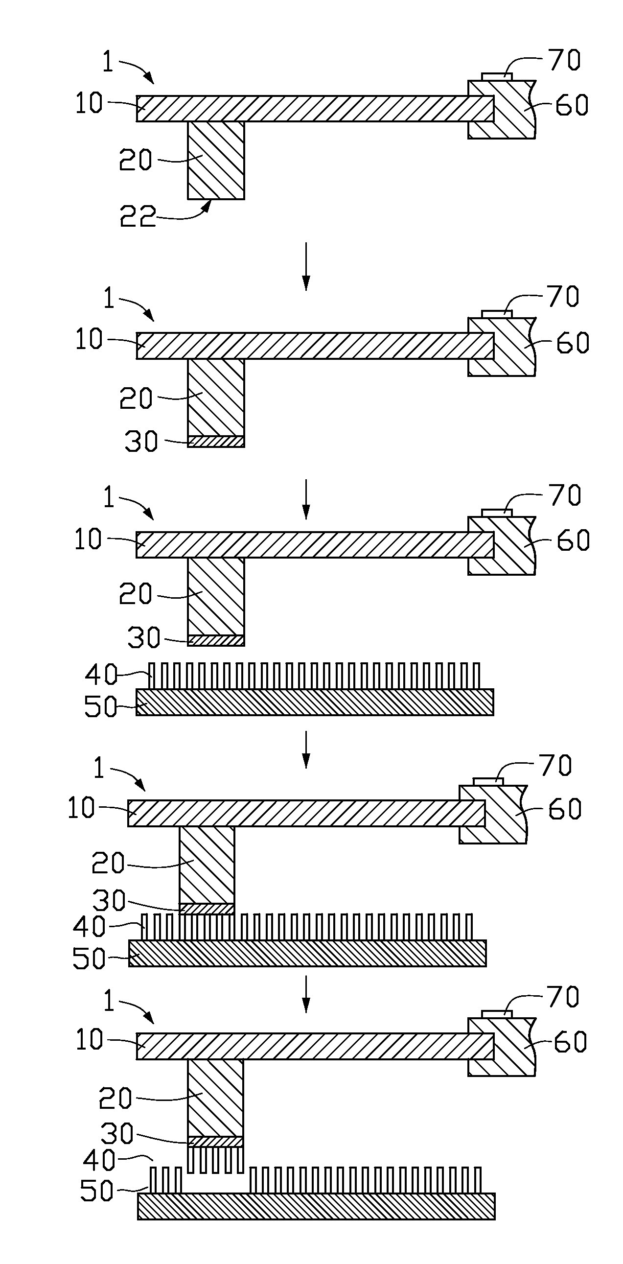
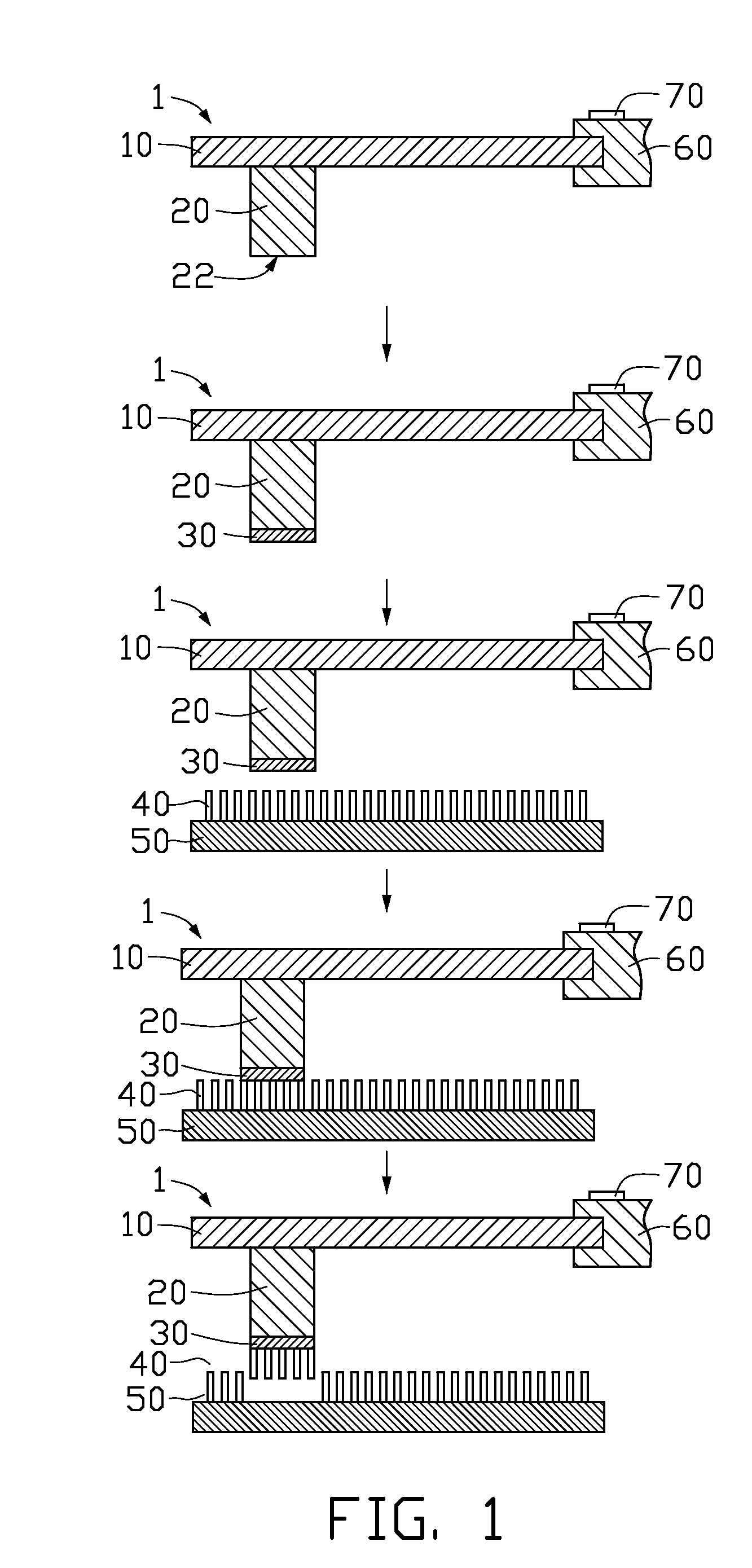
[0017]Referring to FIG. 1, a method for measuring a bonding force between a substrate 50 and a carbon nanotube array 40 formed thereon, wherein the carbon nanotube array 40 includes a plurality of carbon nanotubes, according to a present embodiment, the method includes the following steps:

(a): providing a force gauge 1 including a cantilever 10, a probe 20, a movement mechanism 60, and a force sensor 70, wherein the probe 20 is secured at one end of the cantilever 10 and has a flat surface 22;

(b): forming an adhesive layer 30 on the flat surface 22 of the probe 20;

(c): bringing the probe 20 toward the substrate 50 and, ultimately, into close proximity with the carbon nanotube array 40 by the movement mechanism 60 in order to cause the adhesive layer 30 on the flat su...


PUM


Abstract

A method for measuring a bonding force between a substrate (50) and a carbon nanotube array (40) formed thereon, wherein the carbon nanotube array includes a plurality of carbon nanotubes. A force gauge (1) including a cantilever (10), a flat-surface probe (20), a movement mechanism (60), and a force sensor (70) is provided. The probe is secured at one end of the cantilever. An adhesive layer (30) is formed on the flat surface of the probe. The probe is moved toward the substrate and is brought into bonding contact with the carbon nanotube array by the movement mechanism. The probe is pulled away from the substrate by the movement mechanism, causing the carbon nanotubes adhered thereto to separate from the substrate. The force at separation is detected by the force sensor, and that force can be converted into an average nanotube/substrate bonding force/strength.

Description

BACKGROUND OF THE INVENTION[0001]1. Field of the Invention[0002]The invention relates to a method for measuring a bonding force and, particularly, to a method for measuring a bonding force between a substrate and a carbon nanotube array formed thereon.[0003]2. Description of Related Art[0004]Carbon nanotubes (CNTs) are a carbonaceous material discovered by Iijima, a researcher of NEC Corporation, in 1991. Carbon nanotubes are electrically conductive along their length, are chemically stable, and can each have a very small diameter (much less than 100 nanometers) and a large aspect ratio (i.e., the ratio of length to diameter). Due to these and other properties, it has been suggested that carbon nanotubes can play an important role in fields such as microscopic electronics, field emission devices, thermal interface materials, etc.[0005]Generally, a CNT field emission display device includes a substrate and a carbon nanotube array formed on the substrate. The carbon nanotube array act...

Claims


Application Information

Patent Timeline
IPC IPC(8): G01N3/08G01N19/04
CPCG01N2203/0286G01N19/04
Inventor LIU, KAIJIANG, KAI-LIFAN, SHOU-SHAN
Owner TSINGHUA UNIV
Why Eureka
Try Eureka