Connector for detonator, corresponding booster assembly, and method of use
- Summary
- Abstract
- Description
- Claims
- Application Information
AI Technical Summary
Benefits of technology
Problems solved by technology
Method used
Image
Examples
example 1
Booster Assembly Comprising Connector, with Signal Transmission Line Connected Directly to Detonator
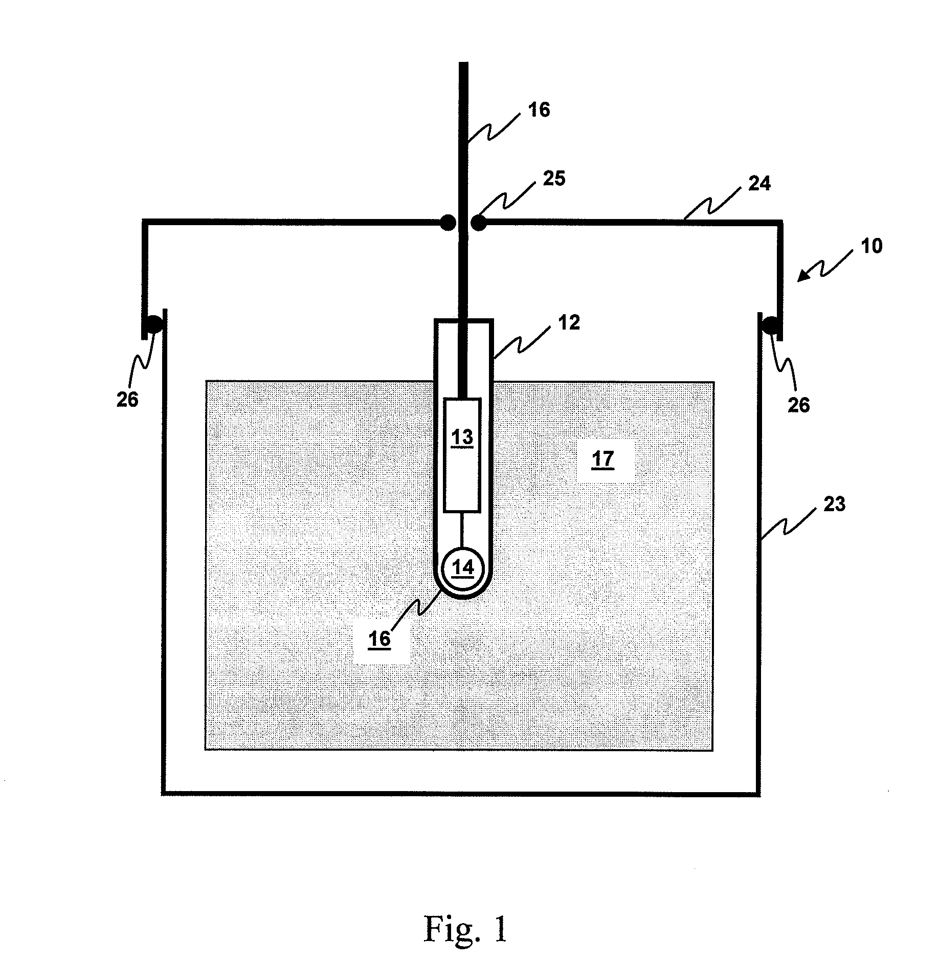
[0060]With reference to FIG. 1, there is illustrated a booster assembly shown generally at 10 comprising a connector, a booster and a detonator. The detonator 12 comprises a shell within which are internal electronic components 13 and a base charge 14 adjacent a percussion actuation end 15. A signal transmission line 16 is connected directly to the detonator, and specifically the internal components 13, via an end of the detonator opposite the percussion-actuation end. The booster includes a booster housing 23 within which is retained a quantity of explosive material 17. Typically, but not necessarily, the explosive material 17 may be in solid or semi-solid form and shaped to allow the detonator to be seated therein, such that the percussion-actuation end of the detonator is embedded in the explosive material. In this way, actuation of the base charge in the detonator may cause subseq...
example 2
Booster Assembly Comprising Connector, with Signal Transmission Line Connected to Electrically Conductive Bridge Elements
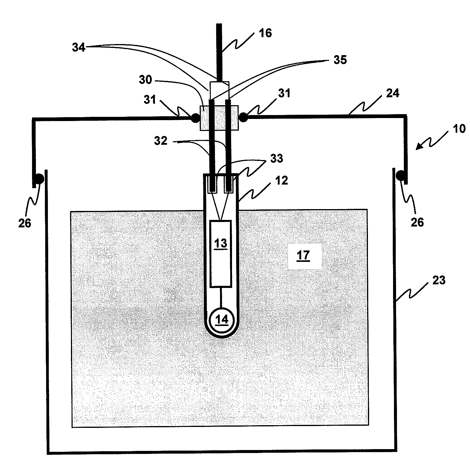
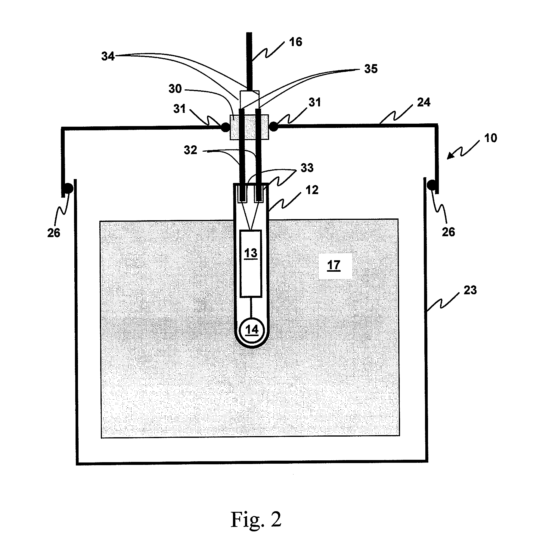
[0062]Turning now to FIG. 2, the embodiment illustrated is similar to that described in Example 1, with the exception that the signal transmission line retainer comprises electrically conducting bridge elements 32, extending through an optionally reinforced section 30 of attachment cap 24. Wires 34 of signal transmission line 16 are attached at interface 35 (e.g. a wire clasp or crimp) to the electrically conductive bridge elements 32. The bridge elements effectively form pins positioned to extend towards the detonator 12, to be received by sockets 33 in the detonator when the attachment cap 24 is properly attached to the booster housing 23. In this way, the bridge elements effectively “plug into” the detonator, thereby to provide electrical contact from the signal transmission line and the detonator. Preferably, attachment of the attachment cap to the housing hel...
example 3
Booster Assembly Comprising Connector, with Detonator Comprising Electrically Conductive Bridge Elements
[0065]Turning now to FIG. 3, there is shown a further embodiment of the booster assembly of the present invention. This booster assembly is similar to that described in Example 2, except that in this embodiment the electrically conductive bridge elements 32 form part of and extend from the detonator shell 12. In this way, the bridge elements 32 are received by sockets 40 forming part of the attachment cap 24, or optionally a reinforced portion 30 thereof. The sockets are in electrical contact with the wires 34 extending from signal transmission line 16, such that electrical contact is established between the signal transmission line and the detonator when the pins 32 are located therein. In accordance with Example 2, the detonator includes no trailing wires and may be transported to the blast site independently from the signal transmission line. Optionally, the connector may be fa...
PUM
 Abstract
Description
Claims
Application Information
 - R&D
- Intellectual Property
- Life Sciences
- Materials
- Tech Scout
- Unparalleled Data Quality
- Higher Quality Content
- 60% Fewer Hallucinations
Browse by: Latest US Patents, China's latest patents, Technical Efficacy Thesaurus, Application Domain, Technology Topic, Popular Technical Reports.
© 2025 PatSnap. All rights reserved.Legal|Privacy policy|Modern Slavery Act Transparency Statement|Sitemap|About US| Contact US: help@patsnap.com


