Constant-speed multi-pressure fuel injection system for improved dynamic range in internal combustion engine

a fuel injection system and multi-pressure technology, applied in the field of engines, to achieve the effect of prolonging the life of the pump, avoiding excess fuel and pressure build-up, and constant fuel pressur

Inactive Publication Date: 2008-07-24
TMC
View PDF51 Cites 17 Cited by
  • Summary
  • Abstract
  • Description
  • Claims
  • Application Information

AI Technical Summary

Benefits of technology

[0024]This invention describes the structure and process of fuel injection delivery systems which create multi-pressure-levels on-demand instantly by restricting the fuel flow at a given steady fuel pump speed. This increases the dynamic range of fuel injection and minimizes fuel pressure fluctuation. Hence, the same engine that incorporates the invention is capable of doing the following: (1) Delivering more power instantly at peak load on-demand, which accelerates the vehicle from stand still to 60 miles per hour in seconds; (2) Reducing the idle speed with the engine still running smoothly, which saves fuel, improves city-driving mileage, and further reduces exhaust when idle; (3) Not changing the fuel tank temperature regardless of how long the engine is in operation; and (4) Enhancing the life of the fuel pump because the pump is running at a constant speed without frequent acceleration / deceleration. Although fuel saving and exhaust control may not seem much to a single vehicle, the cumulative effect should be noticeable in a traffic jam, or anywhere large number of vehicles are crawling with engines running. The invention can be applied to internal combustion engines used in automobiles, airplanes, and diesel engines. Thus, it saves fuel to achieve better city-driving mileage. Most of the existing vehicles already in operation for years can also be modified with minimum effort to achieve a reduced idle speed and still be able to run smoothly. When the invention is applied to a large number of vehicles, the public can enjoy the cumulative effect of cleaner air in metropolitan areas.
[0026]In addition, a fuel-return line diverts a small portion of fuel from the output of the pump (or from the main filter) to the fuel tank to stabilize the fuel system at the predetermined pressure. In other words, the fuel-return line system minimizes fuel pressure fluctuation caused by pump metering action. It also takes away the need to bleed the excess hot fuel at the fuel rail and return it to the fuel tank to avoid pressure built-up at the fuel rail. Without hot fuel returning to the tank, the temperature in the fuel tank will remain unchanged regardless of how long the vehicle is in operation.
[0027]Depending upon the operator's desire and sensor signals from the engine, such as, but not limited to, airflow, engine speed, torque, and temperature, the fuel system can be switched from one steady state to another state at a new pressure level almost instantly without changing the drive (or speed) of the fuel pump. The stabilization of fuel pressure allows a microprocessor to predict a proper fuel injection pulse width for delivering the desired amount of fuel per pulse. It also minimizes the guessing processes to deliver a proposed fuel quantity per pulse in the split injection process commonly used in a diesel engine.
[0028]An important objective of this invention is the capability to change the fuel pressure from one steady state to another state instantly and precisely, while the pump is running at a constant speed. The pressure at each state is steady with minimum pressure fluctuation. It assures a more accurate estimate of the amount of fuel to be delivered to the engine.
[0031]Yet a further objective of this invention is to constantly circulate fuel through the fuel-return line to maintain a constant fuel pressure and to avoid excess fuel and pressure built-up at the fuel-rail. Thus, hot fuel from the fuel rail does not need to return to the fuel tank and the temperature in the tank will remain unchanged regardless of how long the vehicle is in operation. Constant fuel pressure also assures a more predictable amount of fuel injected per pulse.
[0032]All of these objectives can be achieved while the fuel pump is running at a constant speed (or the drive voltage applied to the fuel pump is set at a constant value well within a comfortable linear operating range of the fuel injector). Because the fuel pump is not subjected to frequent and sudden acceleration / deceleration, the life of the pump may be prolonged.

Problems solved by technology

Although fuel saving and exhaust control may not seem much to a single vehicle, the cumulative effect should be noticeable in a traffic jam, or anywhere large number of vehicles are crawling with engines running.

Method used


Image

  • Constant-speed multi-pressure fuel  injection system for improved dynamic  range in internal combustion engine
  • Constant-speed multi-pressure fuel  injection system for improved dynamic  range in internal combustion engine
  • Constant-speed multi-pressure fuel  injection system for improved dynamic  range in internal combustion engine

Examples


Embodiment Construction

[0040]While the specification concludes with claims particularly pointing out and distinctly claiming the subject matter which is regarded as the invention, the invention will now be further described by reference to the following detailed description of preferred embodiments taken in conjunction with the above-described accompanying drawings.

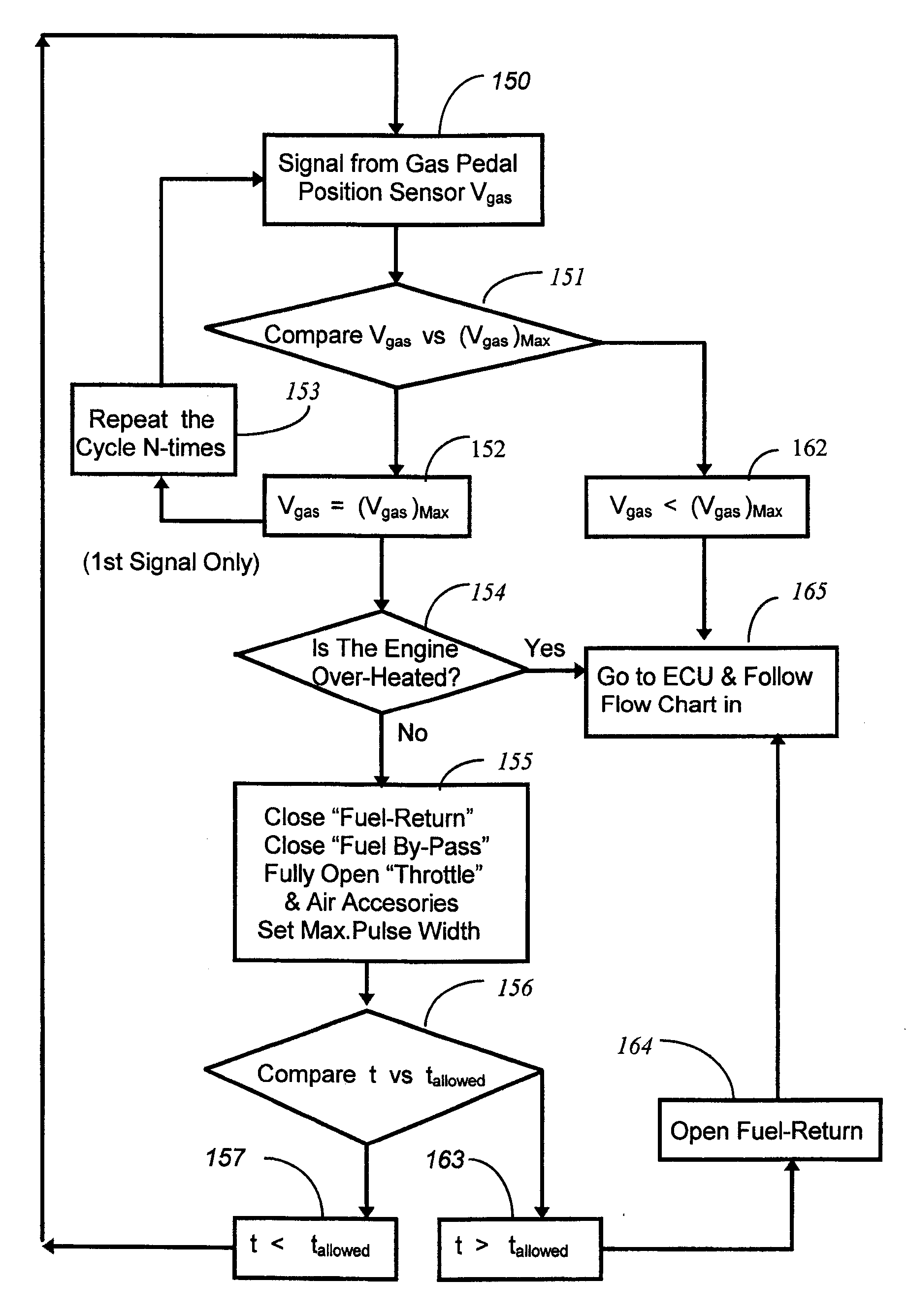
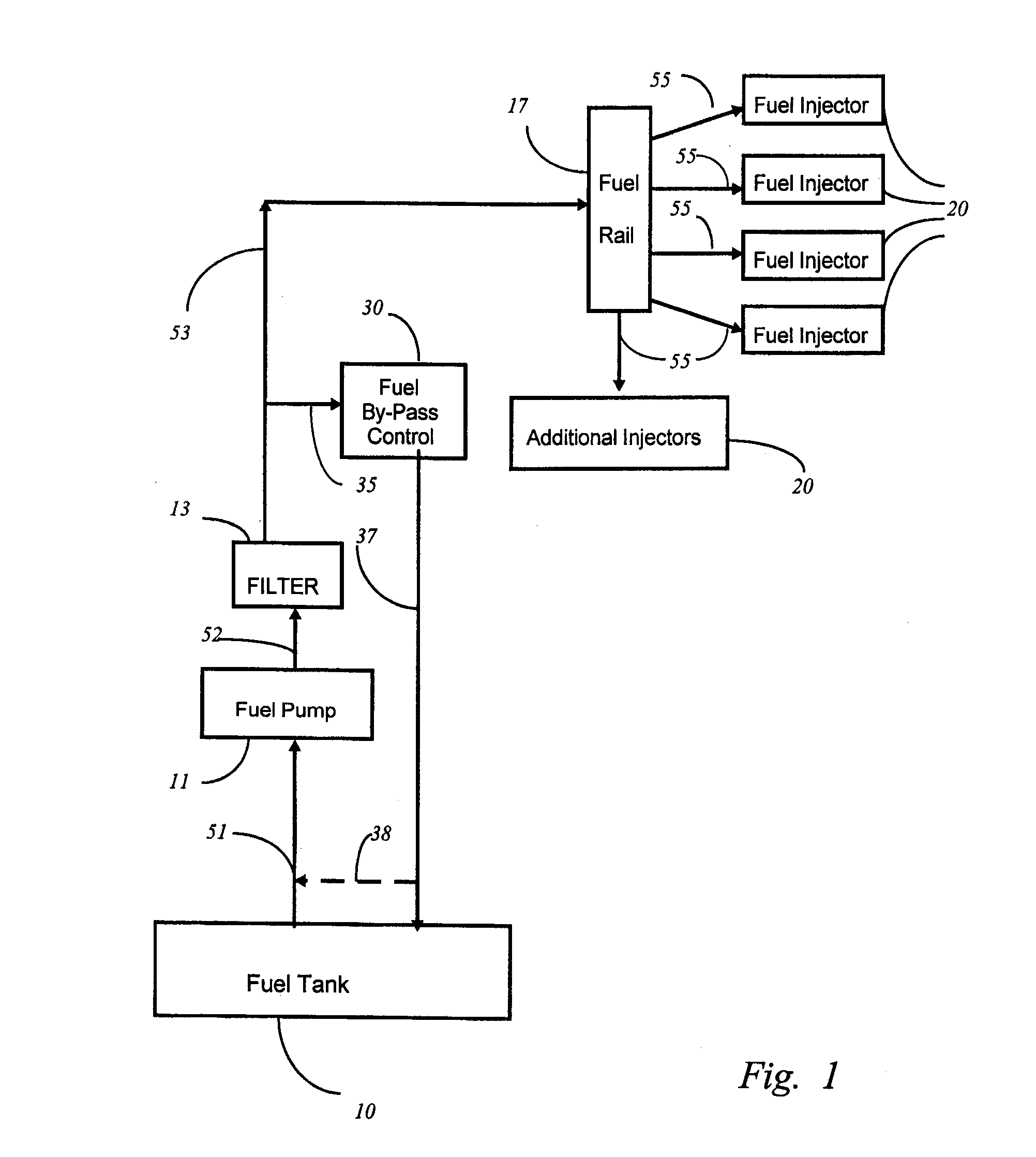
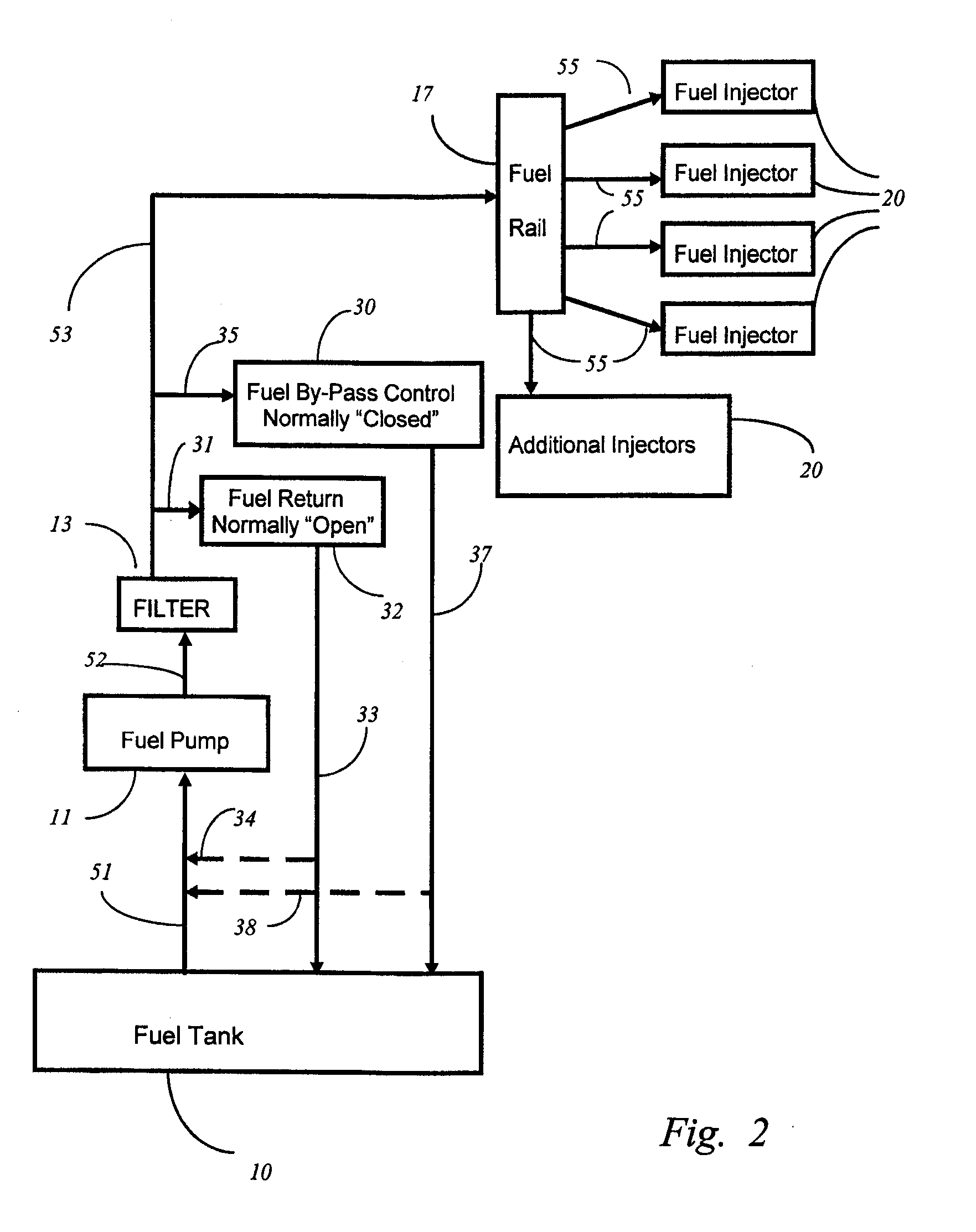
[0041]The structures of fuel injection systems of the current invention are shown in FIG. 1 and FIG. 2. The illustration of its operations and its properties will refer to both figures. Not shown in those figures yet well understood to technical professionals in microelectronics is the set-up of microelectronics used to control the system. An embedded controller, a microprocessor, or a programmable logic circuit can be used as the brain. It may be a standalone unit, or a subroutine of the Engine Management Control (or ECU) of the vehicle. The program may be embedded in ROM, PROM, EPROM, or other conventional storage media like hard disk, CD-ROM...


PUM


Abstract

A fuel injection system operates under a predetermined substantially constant pump speed and creates multi-pressure levels by diverting the fuel flow. Fuel pressure can be switched from one steady pressure level to another level on-demand instantly. This superimposes and overlaps typical fuel injection events in the linear operating ranges under different pressure levels, significantly increasing the fuel injection dynamic range. The dynamic range is further increased when another predetermined constant pump speed is assigned. Thus, the system saves fuel and reduces exhaust emission in city driving when gas pedal is released including idle. The same system can instantly deliver additional fuel on-demand for extra power beyond engine rating producing a sport-car-like performance.

Description

PRIORITY CLAIM[0001]This application is a continuation U.S. patent application Ser. No. 10 / 143,657, filed on May 10, 2002, which is hereby incorporated by reference.FIELD OF THE INVENTION[0002]This invention relates to engines, specifically a fuel system used for engines making use of a fuel injection system.BACKGROUND OF THE INVENTION[0003]Engine emission, such as auto emission, is one of the most contributing factors to air pollution. It is most noticeable in metropolitan areas during traffic jams, and around airports where numerous airplanes are idling in the secondary runway for 20 to 40 minutes on the average before taking off. Reducing the idle speed in internal combustion engines will save fuel when an engine is not doing much work other than keeping it alive. It also reduces exhaust emission, which converts to smog. The problem is most serious in metropolitan areas because there are more than 230 million units of light vehicles in the U.S. as of 2005, most of which are conce...

Claims


Application Information

Patent Timeline
Patent Type & Authority Applications(United States)
IPC IPC(8): F02M69/18F02M69/54F02D41/04F02M51/02F02D33/00F02M37/04F02D41/32F02D41/38F02M37/00F02M63/02F02M69/00
CPCF02D33/006F02D41/3836F02M63/0225F02M37/0052F02D41/3845
Inventor HOU, SHOU L.
Owner TMC
Why Eureka
Try Eureka