
Cold field emitter

a technology of electron emitters and cold field, which is applied in the manufacture of electrode systems, electric discharge tubes/lamps, instruments, etc., can solve the problems of inconvenient use of cold field emitters in electron microscopy, inability to meet the needs of use, and interrupt the operation of electron microscopes or other equipment. achieve the effect of improving stability

Active Publication Date: 2008-07-24
FEI CO
View PDF9 Cites 19 Cited by
  • Summary
  • Abstract
  • Description
  • Claims
  • Application Information

AI Technical Summary

Benefits of technology

[0009]An object of the invention is to provide a cold field electron emitter with improved stability.
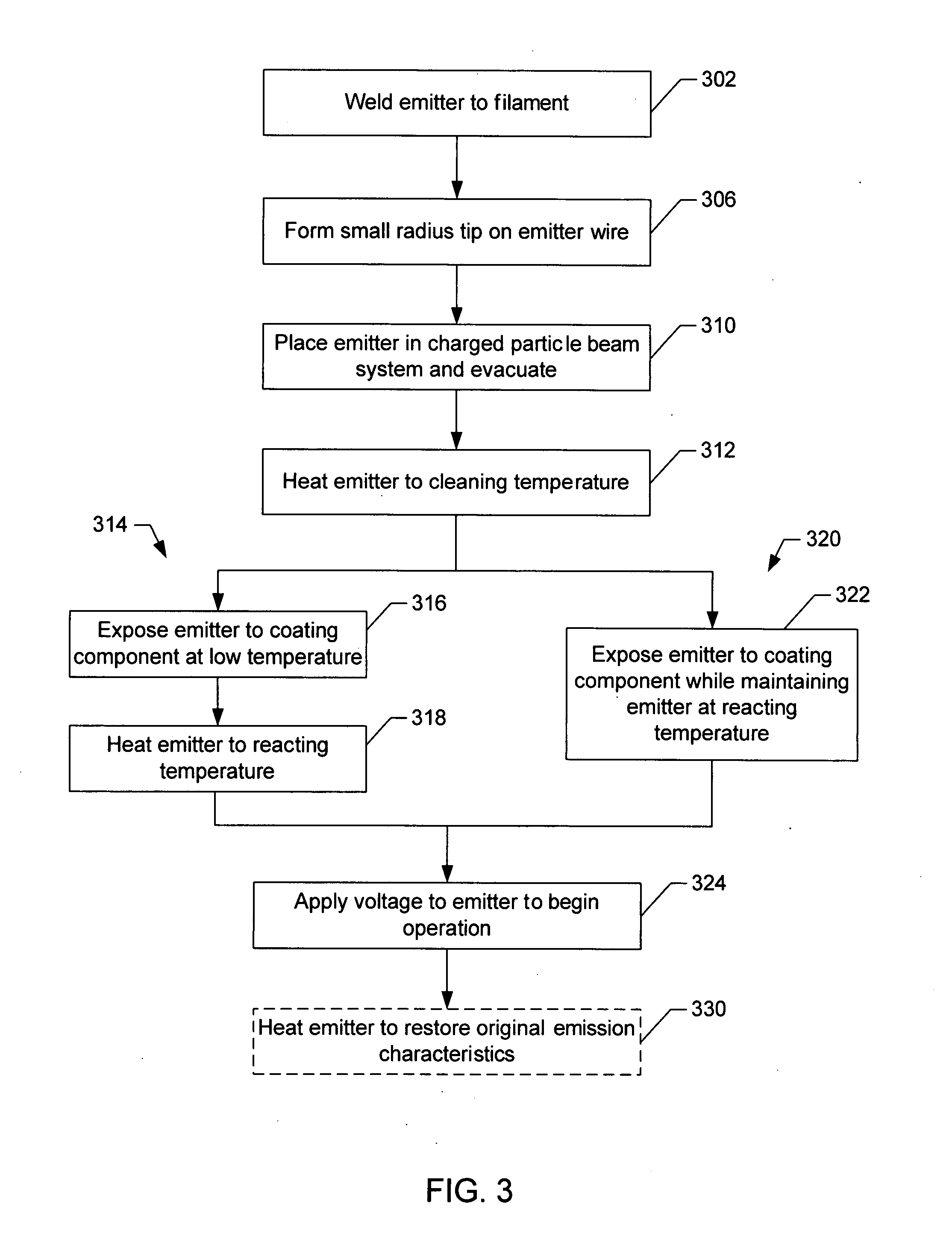
[0010]This invention comprises a cold field electron emitter having a coating that provides improved stability. The invention also includes a method of making a cold field electron emitter and a method of emitting electrons. In a preferred embodiment, the coating is thought to reduce the adsorption of residual gases onto the emitter. A preferred cold field emitter can operate at significantly greater pressure than prior art cold field emitters and provides improved stability.

Problems solved by technology

Cold field emitters are not commonly used in electron microscopy, however, because of both long term and short term emission instability.
Although electron beam columns operate in a vacuum, the vacuum is not perfect, and some residual gas molecules are always present.
Heating the cold field emitter, however, interrupts the operation of electron microscope or other equipment in which the emitter is installed.
Also, heating the emitter to clean the tip tends to blunt the tip, as atoms in the emitter rearrange themselves to reduce the surface energy.
The lower pressure, however, is more difficult to achieve.

Method used


Image

  • Cold field emitter
  • Cold field emitter
  • Cold field emitter

Examples


Embodiment Construction

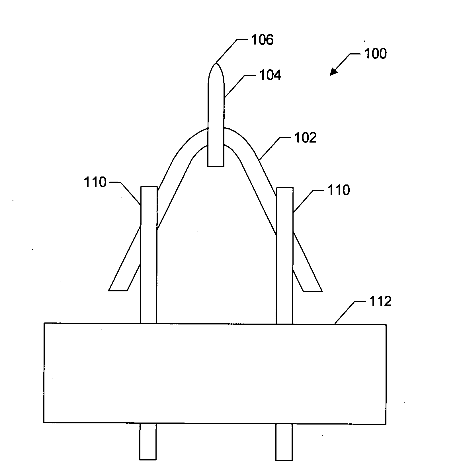
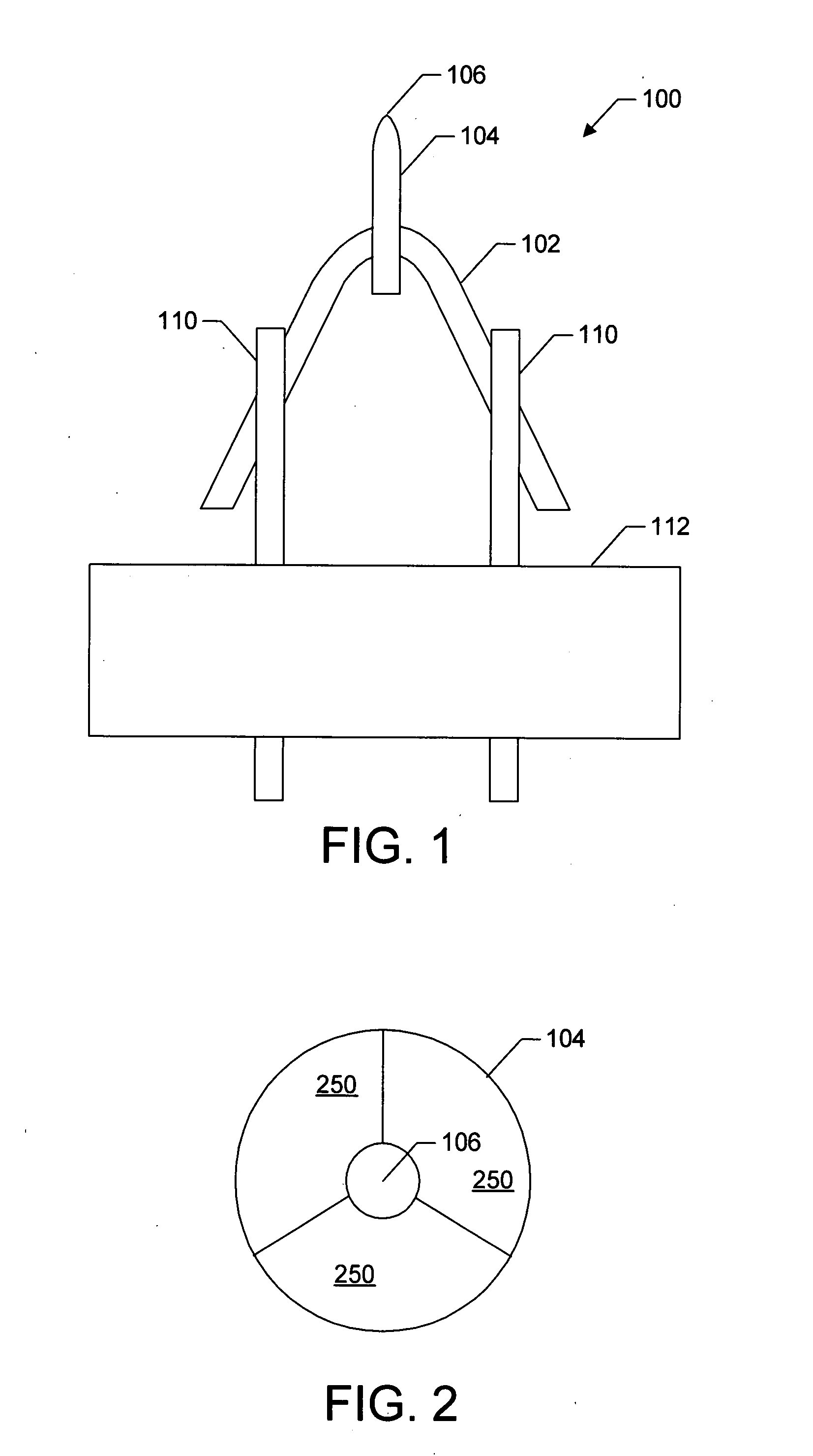
[0018]FIG. 1 shows a cold field electron source 100 embodying the invention. Cold field emitter 100 includes a filament 102 that supports and heats an emitter 104 having a tip 106 from which the electrons are emitted. Tip 106 has as small a radius as can be practically constructed, preferably less than 500 nm, more preferably less than 200 nm, and most preferably less than, or about, 100 nm. A heating current can be supplied to filament 102 through electrodes 110 that penetrate a base 112. Emitter 104 is heated as explained below as part of its preparation for operation, but is not typically heated during operation.

[0019]Emitter 104 preferably comprises a base material of a single crystal of a metal oriented typically with the , , , or crystal direction aligned along the emitter axis. Emitter 104 typically comprises tungsten, tantalum, rhenium, molybdenum, iridium, other similar metals or alloys of these metals. A preferred emitter base material is conductive, non-magnetic, has a l...


PUM


Abstract

A stable cold field electron emitter is produced by forming a coating on an emitter base material. The coating protects the emitter from the adsorption of residual gases and from the impact of ions, so that the cold field emitter exhibits short term and long term stability at relatively high pressures and reasonable angular electron emission.

Description

[0001]This application claims priority from U.S. Provisional Application No. 60 / 897,369, filed on Jan. 24, 2007, which is hereby incorporated by reference.TECHNICAL FIELD OF THE INVENTION[0002]The present invention relates to electron emitters, and in particular to cold field electron emitters.BACKGROUND OF THE INVENTION[0003]Electron emitters are used to generate electrons that are directed into beams for electron microscopy and other applications. Electron microscopy includes scanning electron microscopy, transmission electron microscopy, and scanning transmission electron microscopy, as well as analytical variations of these techniques. An ideal electron source produces a beam of electrons that can be focused to an extremely small spot with sufficient current to provide rapid, consistent data collection. Such an electron source is typically characterized by low energy spread among the emitted electrons, high brightness, and long-term stability.[0004]To be freed from a solid surfa...

Claims


Application Information

Patent Timeline
IPC IPC(8): H01J1/13
CPCH01J1/3044H01J9/025H01J37/073H01J2237/06341H01J2201/30446H01J2237/06316H01J2201/30426
Inventor TESSNER, THEODORE CARLSCHWIND, GREGORY A.SWANSON, LYNWOOD W.
Owner FEI CO
Learn More