
High quality factor, low volume, air-core inductor

a technology of aircore and inductor, applied in the field of aircore inductors, can solve the problems of increasing resistance and increasing inductive heating of conductors, and achieve the effects of increasing surface area, reducing resistance, and increasing surface area

Inactive Publication Date: 2008-07-24
GENERAL ELECTRIC CO
View PDF13 Cites 27 Cited by
  • Summary
  • Abstract
  • Description
  • Claims
  • Application Information

AI Technical Summary

Benefits of technology

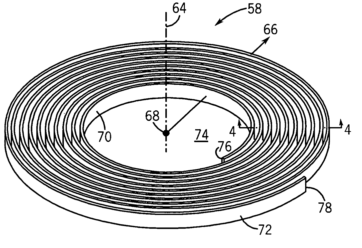
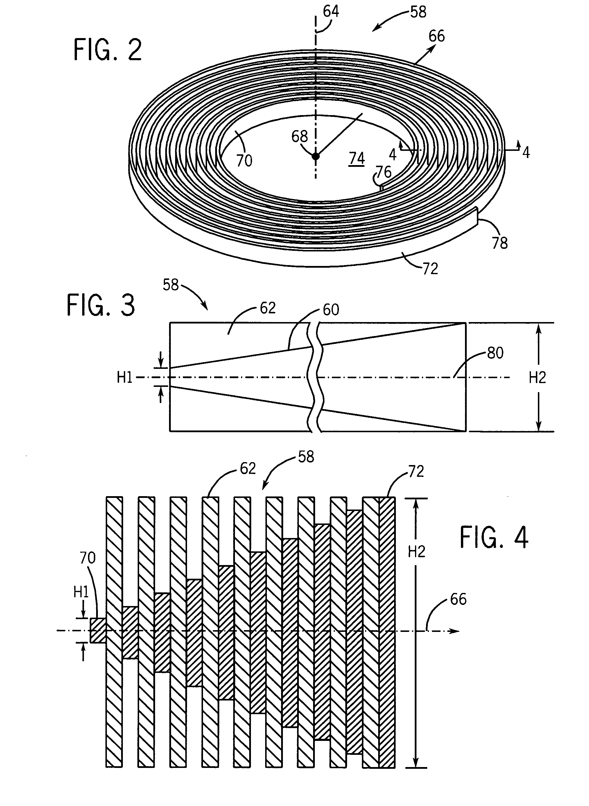
[0009]In one aspect of the present technique, a spirally-wound inductor having a tapered conductor is presented. The height of the conductor increases from a smaller height near the center of the inductor to a greater height at the outer edge of the inductor. Typically, increasing the surface area of a conductor lowers its resistance. However, when the conductor is exposed to a varying magnetic field, a greater surface area will cause greater inductive heating in the conductor and a rise in resistance. Inductive heating occurs when there are variations in the magnetic field to which a conductor is exposed, which induces eddy currents to flow in the conductor. The eddy currents cause the temperature of the conductor to rise, which causes the resistance of the conductor also to rise.
[0010]In the spirally-wound inductor, the magnetic field is strongest near the center and weakest at the outer edge. Having a smaller height near the center reduces the surface area of the conductor that is perpendicular to the magnetic field where the magnetic field is strongest. This reduces inductive heating of the conductor. Therefore, by reducing the amount of inductive heating, the rise in resistance of the inductor that is caused by inductive heating is reduced. By increasing the height of the conductor as the strength of the magnetic field, and inductive heating, decreases, the resistance of the conductor is lowered by the increase in surface area to a greater extent than the inductive heating acts to increase the resistance.

Problems solved by technology

However, when the conductor is exposed to a varying magnetic field, a greater surface area will cause greater inductive heating in the conductor and a rise in resistance.

Method used


Image

  • High quality factor, low volume, air-core inductor
  • High quality factor, low volume, air-core inductor
  • High quality factor, low volume, air-core inductor

Examples


Embodiment Construction

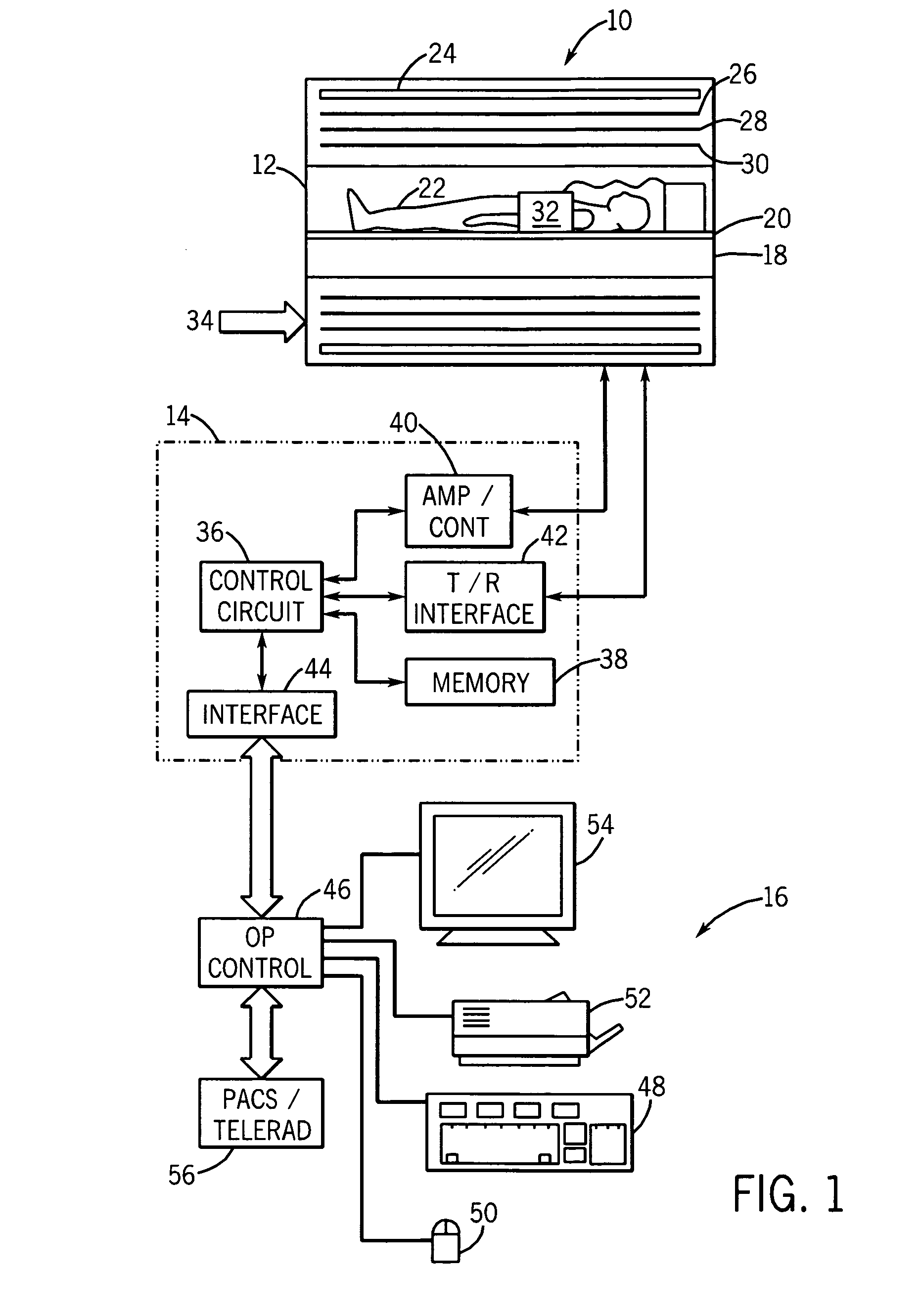
[0022]Turning now to the drawings, and referring generally to FIG. 1, a magnetic resonance (“MR”) system 10 is illustrated. The illustrated MR system 10 including a scanner 12, scanner control system 14, and an operator interface station 16. While MR system 10 may include any suitable MR scanner or detector, the illustrated system includes a full body scanner comprising a patient bore 18 into which a table 20 may be positioned to place a patient 22 in a desired position for scanning.

[0023]A primary magnet coil 24 is provided for generating a main magnetic field that is aligned generally with patient bore 18. A series of gradient coils 26, 28 and 30 are arranged around the patient bore 18 to enable controlled magnetic gradient fields to be generated during examination sequences, as will be described more fully below. In this embodiment, a radio frequency (“RF”) coil 32 is coupled to scanner control system 14 to transmit and receive RF pulses. The RF coil 32 transmits an RF pulse into...


PUM

PropertyMeasurementUnit
Diameteraaaaaaaaaa
Magnetic fieldaaaaaaaaaa
Lengthaaaaaaaaaa

Abstract

A spirally-wound inductor having a tapered conductor. The height of the conductor increases from a smaller height near the center of the inductor to a greater height at the outer edge of the inductor. A spherically-shaped inductor and methods for manufacturing the spherically-shaped inductor. The spherically-shaped inductor has a series of coils that increase in diameter from each end toward the middle.

Description

BACKGROUND[0001]The invention relates generally to inductors, and more particularly to air-core inductors having different diameter coils and the techniques for making them.[0002]Many electrical devices use inductors. An inductor is a passive electrical device that is employed in electrical circuits because of its property of inductance. An electric current flowing through a conductor will produce a magnetic field. An inductor is typically arranged to “store” the magnetic field produced when an electrical current flows through it and, conversely, can produce a current from breakdown of the stored magnetic field when the initial current is removed. A typical inductor is wound as a solenoid and resembles a spring or helical winding. It consists of wire wound into a series of coils, forming a cylinder. The magnetic field generally surrounds the coils of wire when current is applied, in accordance with the right hand rule.[0003]Real inductors are not 100% efficient. They do not convert ...

Claims


Application Information

Patent Timeline
IPC IPC(8): H01F37/00H01F5/00H01F41/04
CPCG01R33/34G01R33/3621G01R33/422H01F5/00H01F7/20Y10T29/4902H01F27/2847H01F27/2871H01F27/34H05B2214/04H01F17/02
Inventor DE ROOIJ, MICHAEL ANDREWBURDICK, WILLIAM EDWARDROSE, JAMES WILSON
Owner GENERAL ELECTRIC CO
Learn More