
Vehicle state information transmission apparatus using tactile device

a technology of vehicle state and information transmission, which is applied in the direction of repeater circuits, frequency-division multiplexes, instruments, etc., can solve the problems of response time lag, insufficient audio warning from the warning device b>504/b>, and inability to clearly perceive the driver's voice, etc., to achieve the effect of reducing the weight of the vehicle, and reducing the for

Inactive Publication Date: 2008-07-24
HONDA MOTOR CO LTD
View PDF14 Cites 150 Cited by
  • Summary
  • Abstract
  • Description
  • Claims
  • Application Information

AI Technical Summary

Benefits of technology

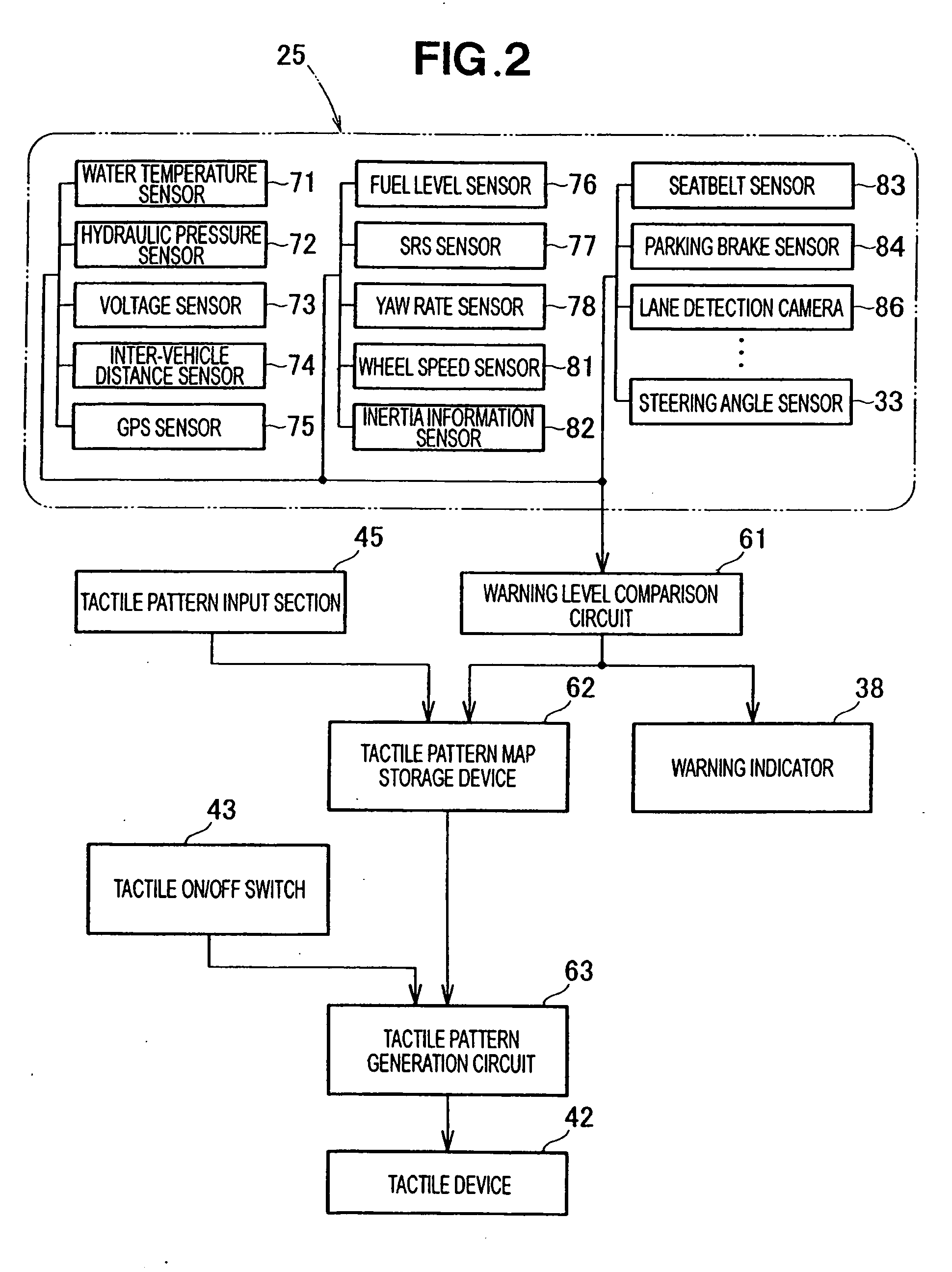
[0013]With this arrangement, since the tactile device is operable in conjunction with the warning means, the vehicle state information representing a warning state of the vehicle is transmitted from the tactile device via the vehicle operating means to the driver as tactile information. With this tactile information transmission, the warning vehicle state information can be well perceived by driver with extremely high reliability even when the vehicle is traveling in loud environments with an audio device operating with full volume and / or the driver is a pregnant female which is freed from the obligation to drive with a seat belt securely fastened.
[0014]Preferably, the tactile device is capable of producing a movement of the tactility in different patterns that can be varied based on the information pertaining to the vehicle state detected by the vehicle state detecting device. By thus providing different tactile patterns, the vehicle state information can be transmitted to the driver with improved certainty.
[0019]With this arrangement, since tactile device has a variable action pattern, which is variable in accordance with the travel direction of the vehicle on the basis of information pertaining to the travel direction detected by the travel direction sensor, the drive is allowed to perceive the tactile information indicative of the vehicle state even when the vehicle is traveling reverse. This will significantly improve the driving safety.
[0022]Preferably, the operation means comprises a steering wheel of the vehicle, which has a grip portion for being gripped by the driver. The tactile device is assembled in the grip portion of the steering wheel. The steering wheel further has a guard protrusion disposed in the grip portion and engageable with a hand of the driver to prevent the tactile device from being subjected to undue stress during steering operation.
[0023]The guard protrusion thus provided limits a tendency of the driver's hand to displace in a radial outward direction during steering, which will apply more force to the tactile device assembled in the grip portion. The tactile device is therefore durable and has a long service life.
[0024]Preferably, the operation means comprises an accelerator pedal of the vehicle, and the tactile device comprises a vibration generating mechanism assembled with the accelerator pedal. The vibration generating mechanism directly vibrates the accelerate pedal and is able to transmit vibration of the accelerate pedal directly to the driver's foot. This arrangement allows for the use of the existing accelerating pedal without reconstruction, which will lead to a reduction of the vehicle weight and cost cutting.

Problems solved by technology

However, the foregoing lane departure prevention apparatus (vehicle state information transmission apparatus) 501 is not fully satisfactory in that when the vehicle is traveling along a road with irregular road surface while passing in loud environments or playing an audio device at top volume, both the vibratory motion of the steering wheel shaft 505 and the audio warning from the warning device 504 cannot be clearly perceived by the driver.
The vehicle warning apparatus (vehicle state information transmitting apparatus) 551 of the foregoing construction, however, necessarily involves a response time lag problem due to the use of a working fluid.
With this arrangement, however, since a rear-end collision warning is provided to the driver by way of vibrations produced by repeated tightening of the seatbelt, a reliable perception of such vibratory warning cannot be expected for a pregnant woman driver who has no obligation to fasten a seatbelt, or a driver thickly dressed with a winder sweater and a down-jacket.
However, the thus arranged vehicle state information transmission apparatus (lane keep assistance device) is disadvantageous in that increasing the steering reaction force to take up a lane departure of the vehicle will require a measurable amount of electric power if the steering reaction force is electrically produced, or involve high fuel consumption if the steering reaction force is hydraulically produced.
Furthermore, due to the presence of surface irregularities, undulations, or ruts on the road surface, it is difficult for the driver to perceive whether the steering reaction force is produced by either the lane keep assistance device or the road surface profile.
With this arrangement, however, since the wavy motion produced by the projections 505-508 using the tactile device 504 always travels in the same direction (radially outward direction of the steering wheel) regardless of the angular position (steering angle) of the steering wheel, a problem will occur in that when the steering wheel has been turned more than 90 degrees ahead of the neutral position, the traveling direction of the wavy motion relative to the turning direction of the vehicle 502 is reversed and this reversed condition will continue until the steering angle exceeds 270 degrees.
Reversal of the relation-ship between the two movement directions would confuse the driver and hinders reliable perception of the tactile information by the driver.

Method used


Image

  • Vehicle state information transmission apparatus using tactile device
  • Vehicle state information transmission apparatus using tactile device
  • Vehicle state information transmission apparatus using tactile device

Examples


Embodiment Construction

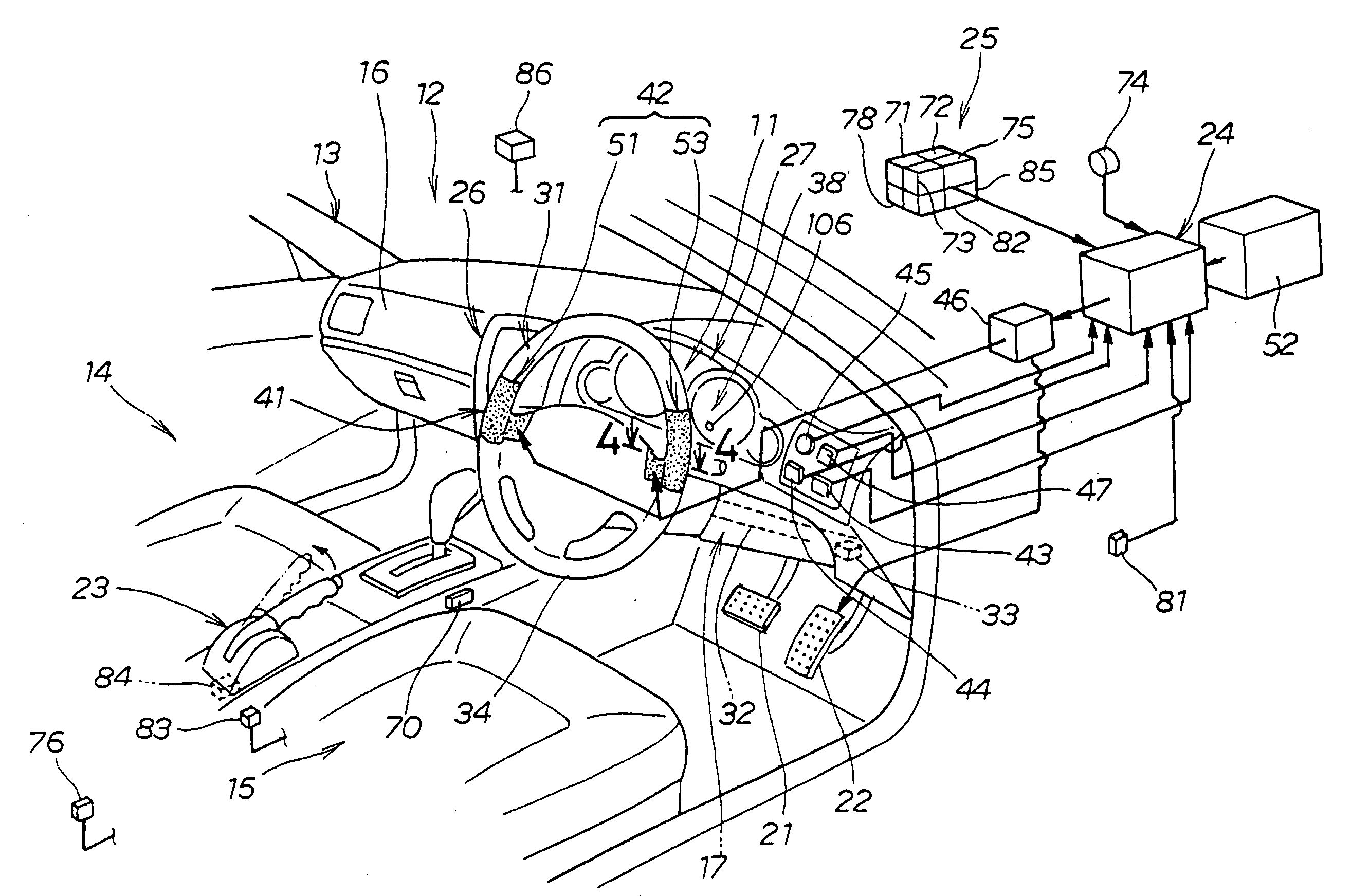
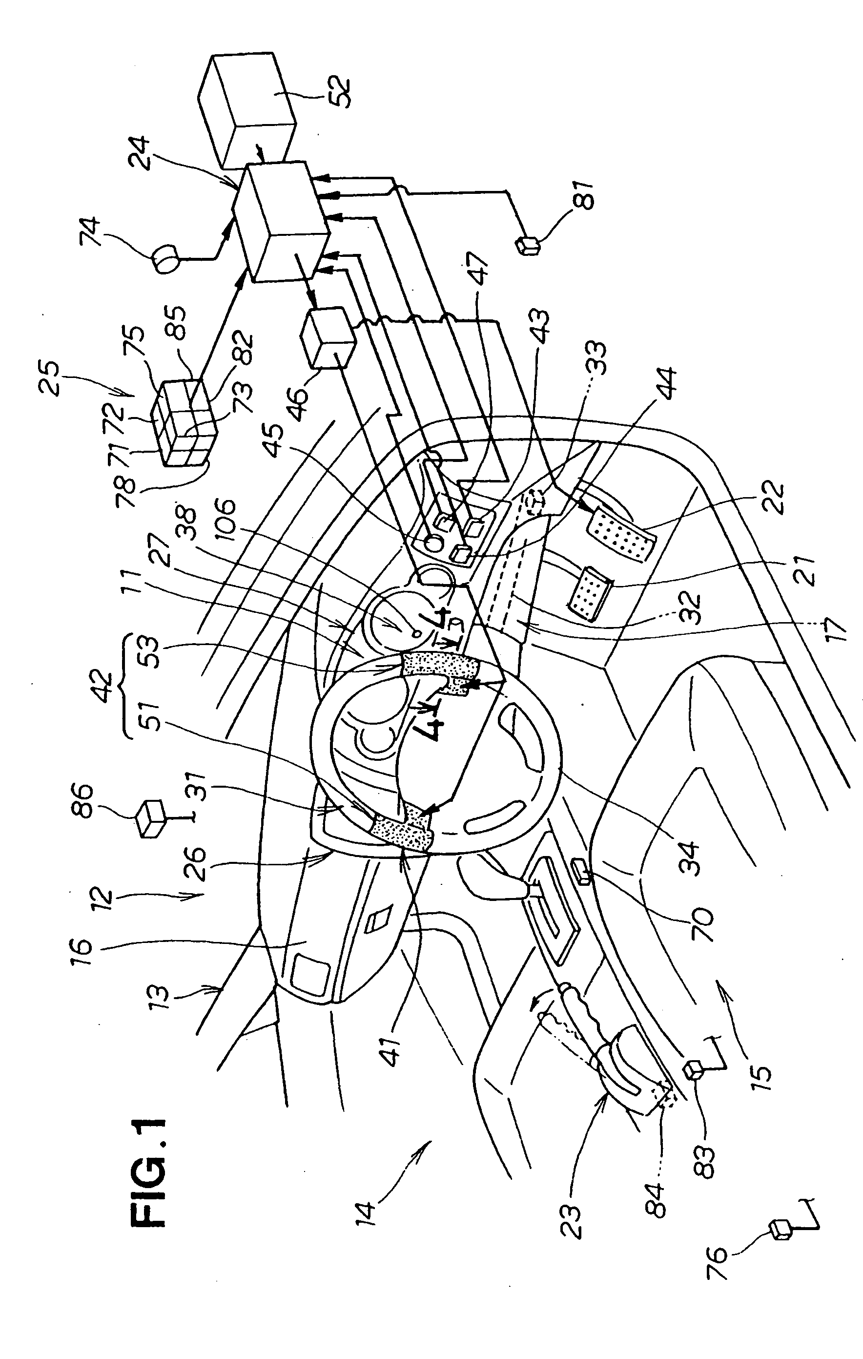
[0065]Referring now to the drawings and FIG. 1 is particular, there is shown a vehicle state information transmission apparatus 11 installed in a vehicle 12 for transmitting vehicle state information to a human driver. The term “vehicle state” is used herein to generally refer to traveling states or behaviors of the vehicle and conditions of various parts of the vehicle as on-vehicle devices.

[0066]As shown in FIG. 1, the vehicle 12 includes a body 13, a passenger compartment 14 defined in the body 13, a driver's seat 15 disposed inside the passenger compartment 14, a dashboard 16 disposed in front of the driver's seat 15, a power steering apparatus 17, a brake pedal 21, an accelerator pedal 2 serving as an operating means actuatable by the driver for operating the vehicle 12, a parking brake lever 23 provided on a left side of the driver's seat 15, an electronic control unit (ECU) 24 for controlling the vehicle 12, a vehicle state detection device 25 for detecting various states or ...


PUM


Abstract

A vehicle state information transmission apparatus includes a warning device for issuing a warning to the driver based on information pertaining to a vehicle state detected by a vehicle state detecting device, and a vehicle state information transmission device for transmitting the information pertaining to the vehicle state detected by the vehicle state detecting device to the driver. The vehicle state information transmission device includes a tactile device, which transmits a change in the vehicle state via a vehicle operating device such as steering wheel to the driver as tactile information. The tactile device is operable in conjunction with the warning means.

Description

FIELD OF THE INVENTION[0001]The present invention relates to an apparatus for transmitting vehicle state information to a driver by way of tactile information produced by a tactile device.BACKGROUND OF THE INVENTION[0002]Various vehicle state information transmission apparatus or systems for transmitting vehicle state information to a driver as tactile information are known as disclosed in Japanese Patent Laid-open Publications (JP-A) Nos. 2005-182406, 2001-080436, 2005-041471, 2001-010518, and 2006-298166.[0003]The vehicle state information transmission apparatus disclosed in JP-2005-182406A, as shown in FIG. 30 hereof, takes the form of a lane departure prevention apparatus 501 comprised of a visual external sensor (CCD camera) 502, a camera (sensor) controller 503, an electronic control unit ECU including a departure determining section, a warning device 504, and a brake hydraulic pressure control circuit operatively connected to the ECU and brake units associated with vehicle wh...

Claims


Application Information

Patent Timeline
IPC IPC(8): B60Q1/00
CPCB60Q9/00B62D15/029B62D1/046G08G1/167B60N2002/981
Inventor TANIDA, KOJIKONDO, SHUGO
Owner HONDA MOTOR CO LTD
Learn More