
Correction Method and Measurement Device For Anti-Stokes Photoluminescence Measurement

a technology of photoluminescence measurement and correction method, which is applied in the field of anti-stokes photoluminescence correction method, can solve the problems of small stokes shift, limited use and sensitivity of traditional fluorescence, and difficulty in detecting the effect of stokes,

Active Publication Date: 2008-07-24
HIDEX
View PDF0 Cites 40 Cited by
  • Summary
  • Abstract
  • Description
  • Claims
  • Application Information

AI Technical Summary

Benefits of technology

The present invention provides a method to correct for error in anti-Stokes photoluminescence measurements in a Foerster-type resonance energy-transfer assay. This is achieved by exciting anti-Stokes photoluminescent molecules with light of a different wavelength and measuring the emission light signal in at least two different time windows. The method can be carried out using a device or a system, and a software product is also provided for the system. The technical effect of the invention is to improve the accuracy of anti-Stokes photoluminescence measurements in a Foerster-type resonance energy-transfer assay.

Problems solved by technology

Traditional fluorescence, however, has several limitations regarding use and sensitivity.
In practice, because the fluorescence phenomenon is relatively common, the fluorescence originating from sample impurities, sample containers and components of the measurement equipment is a problem in bioassays.
Another problem with traditional fluorescence is small Stokes shift, meaning that excitation and emission wavelengths of the fluorescent compound are close to each other.
This makes it difficult to select and limit the measured wavelength range of measurement instruments.
Also time-resolved fluorescence has problems.
Because lanthanides need high-energy photons (short wavelength) for excitation, the required excitation light source is complex and expensive.
Another problem is that to reduce the long-lifetime autofluorescence and to be transparent to the ultraviolet excitation radiation, the employed optical components of the measurement instrument need to be of very high quality, e.g. all lenses must be pure quartz.
A further problem both in traditional and time-resolved fluorescence is the operated wavelength range.
This renders the assays complex and requires expensive instrumentation to carry out the assay automatically.
TR-FRET has specifically a problem with the measurement of the sensitized emission.
Typically, this results in a very weak emission from the acceptor.
Ideally the sensitized emission of the acceptor should be measured simultaneously with the excitation of the donor, this is however not possible with time-resolved fluorescence.
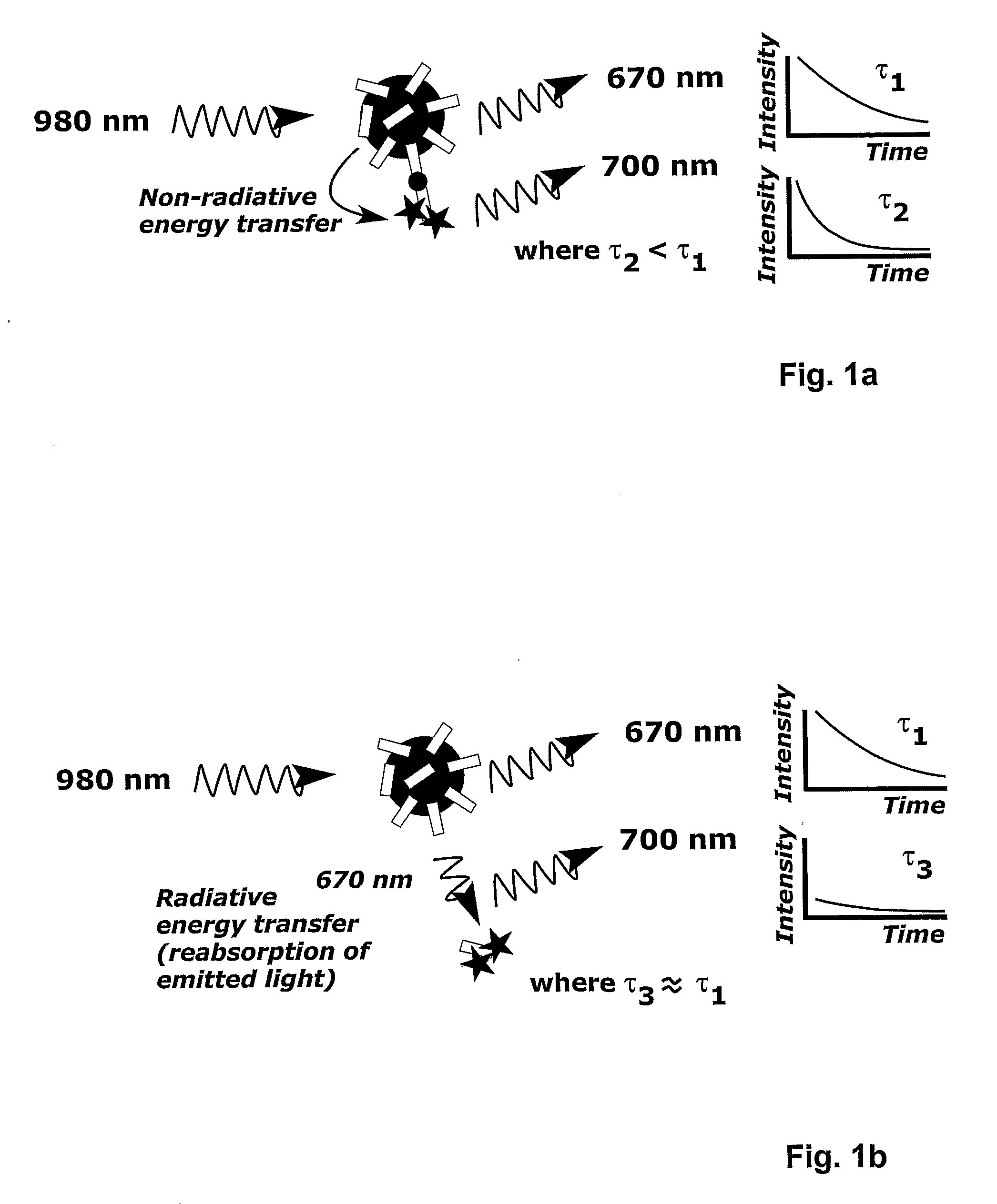
Another problem in the FRET-based bioassays is radiative energy-transfer.
This emission is called radiative energy transfer or non-proximity energy transfer and causes unwanted background to the measured signal.
Perhaps the greatest problem of using time-resolved fluorescence in FRET type assays is due to the fact that after the excitation light pulse has been turned of the emission drops exponentially.
The described methods, however, suffer the problems associated with traditional fluorescence and time-resolved fluorescence.

Method used


Image

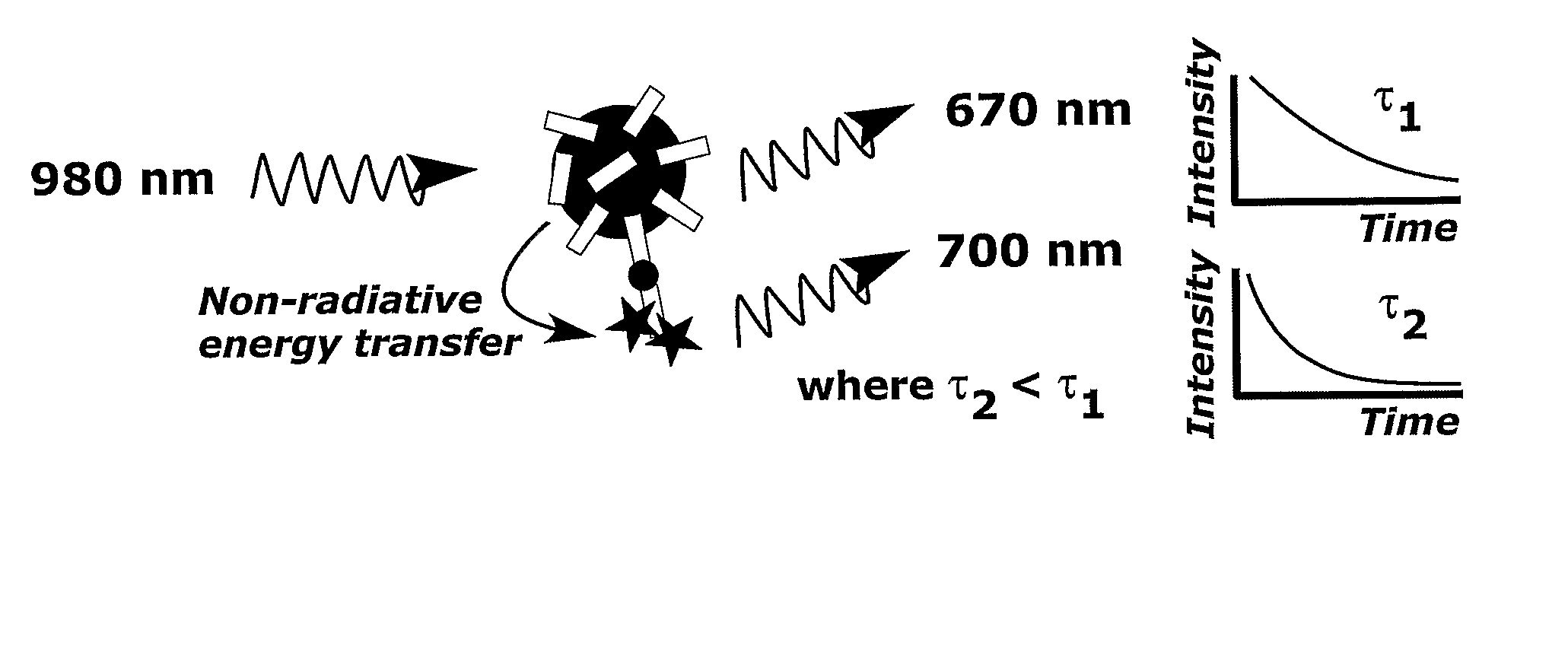
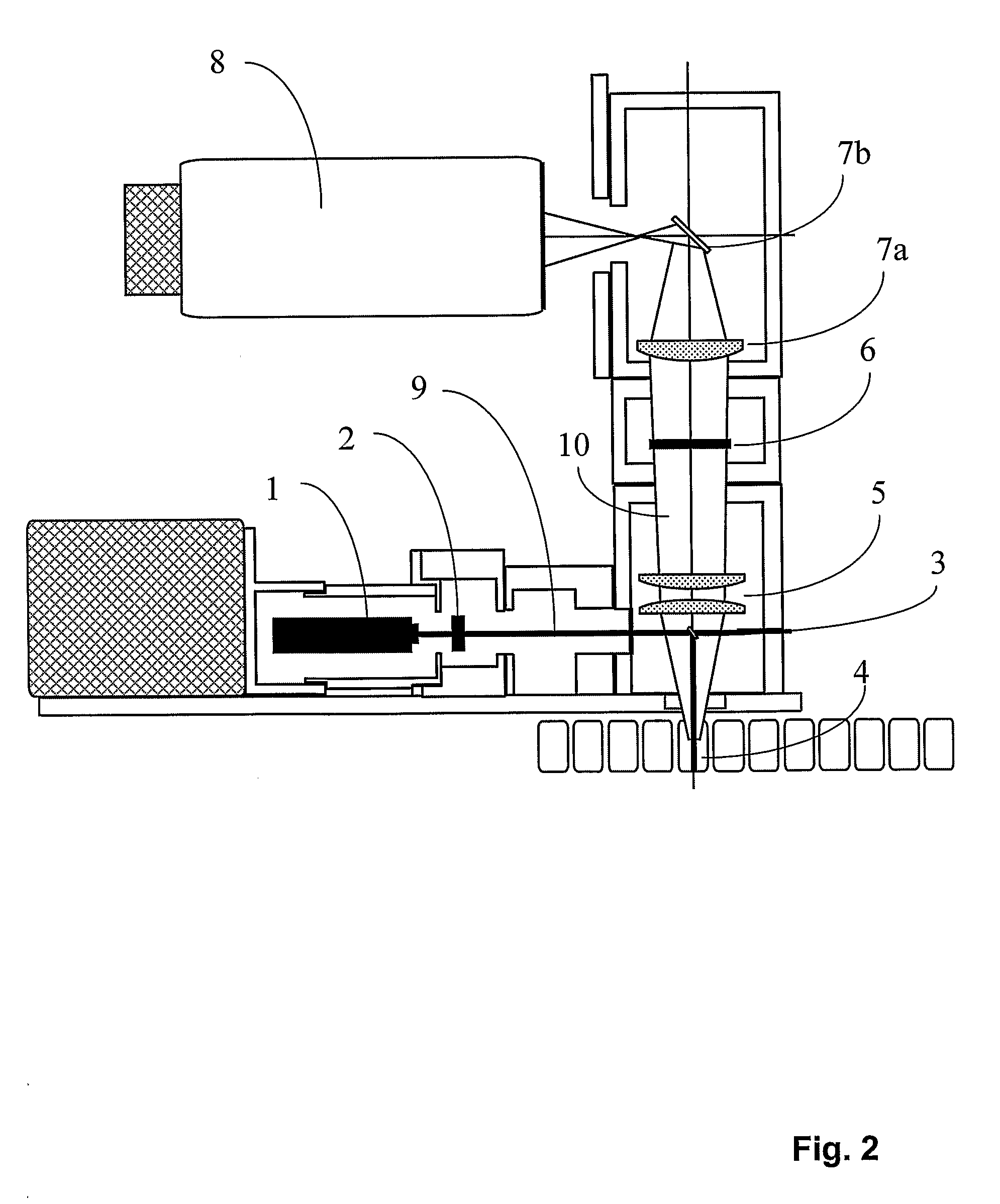
  • Correction Method and Measurement Device For Anti-Stokes Photoluminescence Measurement
  • Correction Method and Measurement Device For Anti-Stokes Photoluminescence Measurement
  • Correction Method and Measurement Device For Anti-Stokes Photoluminescence Measurement

Examples


Embodiment Construction

[0060]Prior are does not describe correction of the sensitized acceptor emission measured without temporal resolution (i.e. simultaneously with excitation) by using a temporal resolution and a life-time analysis of the delayed sensitized acceptor emission signal (measured with a delay after excitation) to separate emission originating from radiative energy transfer and FRET in the signal measured without temporal resolution. What is not known from prior art is that when anti-Stokes photoluminescent donor is used the measurement of the sensitized acceptor emission can be performed simultaneously with the excitation light pulse. This is possible because the measurement does not need to be delayed to reduce the background, as is the case in time resolved fluorescence. Furthermore with the simultaneous continuous excitation and photon counting the donor can be excited again immediately after the excited state of the donor is relaxed. This has not been disclosed in prior art, but is espe...


PUM

PropertyMeasurementUnit
time windowaaaaaaaaaa
timeaaaaaaaaaa
timeaaaaaaaaaa

Abstract

This invention relates to a method to correct for error in an anti-Stokes photoluminescence measurement in a Foerster-type resonance energy-transfer assay. The method comprises the steps of exciting anti-Stokes photoluminescent molecules, ions, phosphors, chelates, or particles, i.e. donors of the assay, with one wavelength or multiple wavelengths of light wherein the wavelength or wavelengths are greater than that of an emission wavelength of acceptor molecules in the assay; measuring emission light signal at a wavelength, which is the emission wavelength of the acceptor molecules in the Foerster-type resonance energy-transfer assay, and which differs from the emission wavelength of the anti-Stokes photoluminescent donor in at least two different time windows; a first time window within the time window defined by the excitation light pulse, i.e. within the time window opening when the excitation light pulse is switched on and closing when the excitation light pulse is switched off, and a second time window to follow the first time window not at all overlapping with the time window defined by the excitation pulse; and correcting the emission light signal measured, comprising signals originating from non-radiative and radiative energy transfer, within the first time window by estimating the ratio of the signals from non-radiative and radiative energy transfer or the signal originating from radiative energy transfer using at least one emission light signal measured in the second time window. This invention also relates to the use of a device according to the method of the invention, a system for carrying out the method and a software product for the system.

Description

FIELD OF THE INVENTION[0001]This invention relates to a method to correct for error in an anti-Stokes photoluminescence measurement and to a device employing the method. This invention relates particularly to a method to correct for radiant energy transfer component in a Foerster-type resonance energy transfer FRET-assay.BACKGROUND OF THE INVENTION[0002]The publications and other materials used herein to illuminate the background of the invention, and in particular, cases to provide additional details respecting the practice, are incorporated by reference.[0003]Photoluminescence and Fluorescence Phenomenon[0004]In traditional fluorescence phenomenon, such as photoluminescence a fluorescent molecule or ion is excited with light. Photons are absorbed by the target molecule or ion and the energy excites the target molecules or ions electrons to a higher energy state. When the excited energy state of the electrons is released, energy is released as a photon emitted by the molecule or io...

Claims


Application Information

Patent Timeline
Patent Type & Authority Applications(United States)
IPC IPC(8): G01N21/64
CPCG01N21/6408G01N21/6428G01N33/582G01N33/542G01N21/6452
Inventor HAASLAHTI, VILLEAALTO, JUHANIOIKARI, TIMOSOUKKA, TERO
Owner HIDEX
Learn More