
Light emitting diode driver

Inactive Publication Date: 2008-07-24
VASTVIEW TECH
View PDF13 Cites 61 Cited by
  • Summary
  • Abstract
  • Description
  • Claims
  • Application Information

AI Technical Summary

Benefits of technology

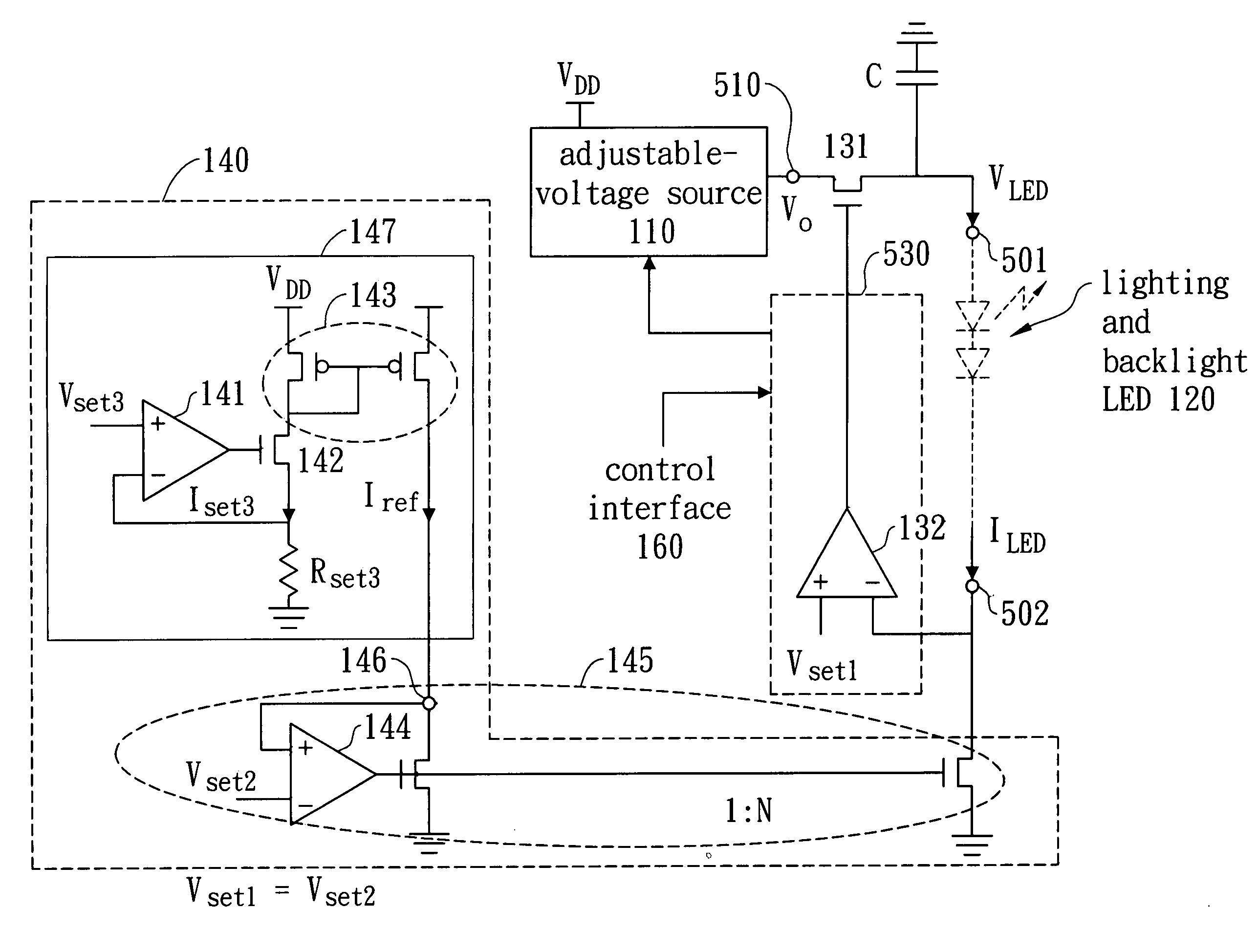
[0006]The main objective of this invention is to provide a controllable driver and a driving system with an excellent stability for LEDs. Except a constant-current technology, a particular technology of voltage adjuster in the present invention can auto adjust appliance's driving voltage to fit different requirements for keeping steady driving current even in facing the possible rise on temperature or voltage desire by certain situations.
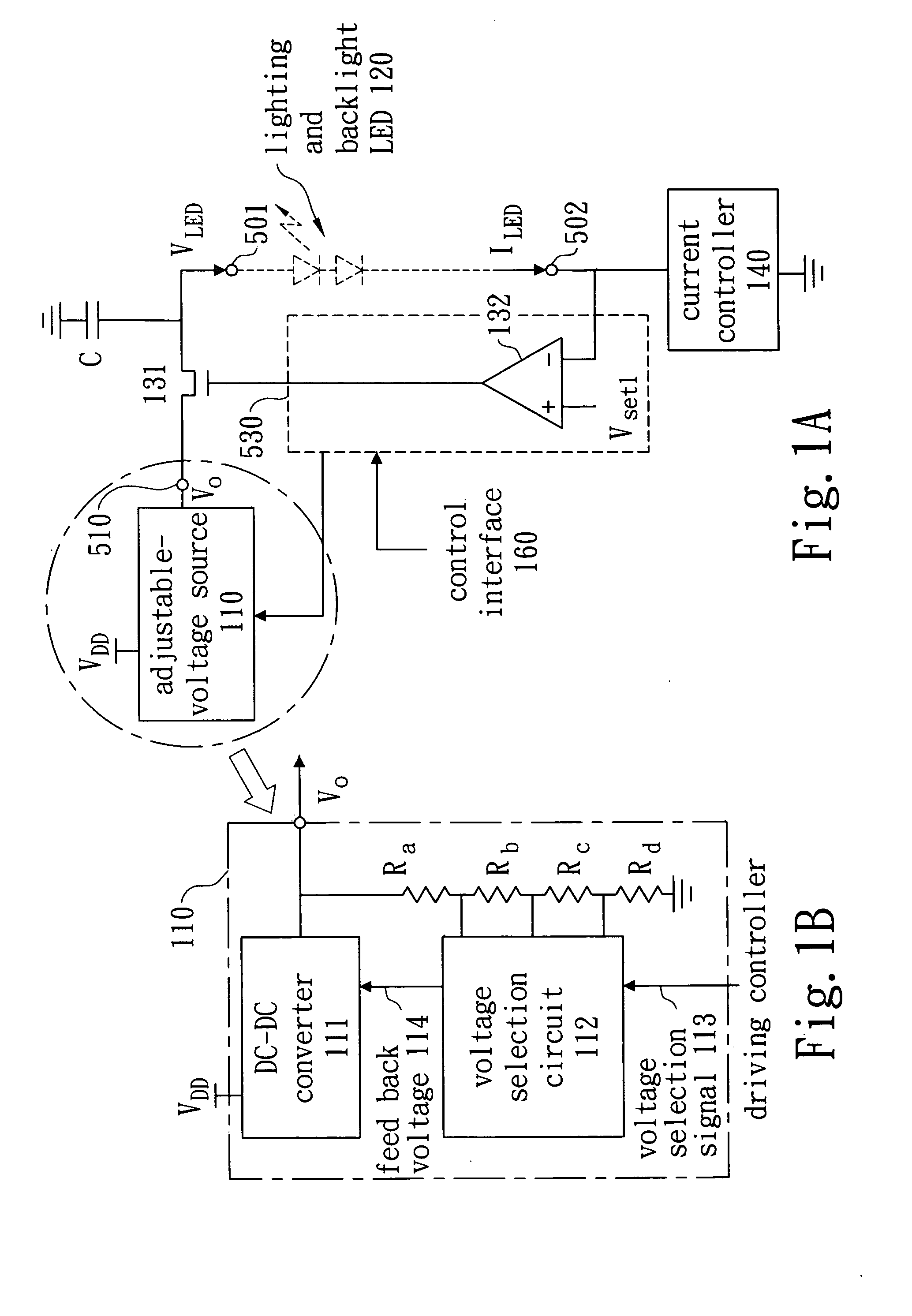
[0008]Further, with the particular technology of voltage adjuster, an additional adjustable-voltage source combined with a user control interface expands the driving system's applicability. Users can select different driving voltages to fit diverse appliance requirements through the control interface. Additionally, an over-temperature and an over-current protection are equipped in the present invention to prevent harms from over-temperature and over-current happenings especially in high power lighting and backlight LEDs.

Problems solved by technology

However, for some delicate appliances (e.g. high power lighting and backlight LEDs), a rise on temperature during emitting, voltage fluctuation, and variation of the LED emitting property from producing will change the steady driving current beyond the settings.
Nevertheless, the chip space for two current mirror with 1:N magnification ratio is too large; and the current clamping is not strong enough to manager possible electrical characters change (e.g. effective resister, I-V curve, and chemical and physical characters change) and the followed voltage desire.
Too complicate situations are still hard to manager for the traditional constant current drivers.

Method used


Image

  • Light emitting diode driver
  • Light emitting diode driver
  • Light emitting diode driver

Examples


Embodiment Construction

[0021]As an embodiment of the invention, a controllable driver 500 to drive a stead current from high voltage Vapp1 501 to low voltage Vapp2 502 in an application 520 comprises: (a) a DC voltage input 510 for DC voltage Vo supply; (b) a 1st field effect transistor (FET) 131 as a voltage adjustor to adjust voltage differential (Vapp1-Vapp2) on the appliance for voltage desire from the steady driving current Iapp requirement by changing its drain-to-source voltage differential; (c) a controller 530 to control gate voltage of the 1st FET; and (d) a current controller 140 to clamp the steady driving current as setting. The controller 532 can is operable to detect voltage variation of the appliance and send negative feedback voltage to gate of the 1st FET in order to auto adjust drain-to-source voltage differential of the 1st FET and compensate the said voltage desire for keeping steady driving current. By this negative feedback circuit, the controllable driver in this invention can auto...


PUM


Abstract

A driving system used for light emitting diodes relating to a controllable driver which can detect the voltage desire from application and adjust driving voltage (Vapp1-Vapp2) automatically in order to reach a steady driving current. Additionally, users can adjust the setting of driving current and the output value of DC voltage source for application with different voltage and current requirements through a control interface. The over-temperature and over-current protections (e.g. cutting off driving current or setting the upper limit of driving current) are also included in the system for prevention of possible harms. In the system, a driving system is also disclosed for integration of all the mentioned functions but no need of massive space and can be used in LED lighting system or LED backlight system for constant power emitting.

Description

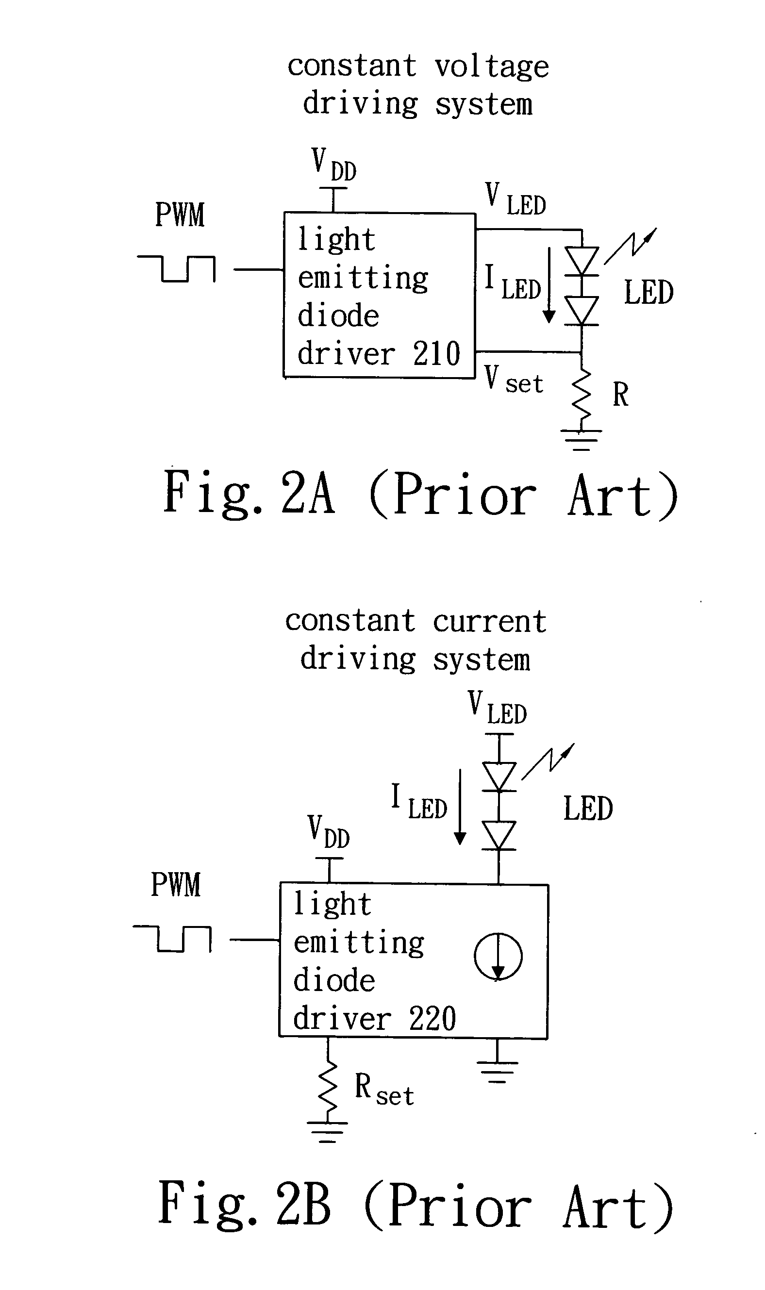
BACKGROUND OF THE INVENTION[0001]1. Field of the Invention[0002]This invention generally relates to a light emitting diode (LED) driver, and more specifically relates to a driving control technology of auto voltage adjustment for keeping steady driving current. The present invention is operable to drive high power LEDs (e.g. lighting LED and backlight LED).[0003]2. Description of the Prior Art[0004]In traditionally industrial producing, there are two methods for a constant current driver: one is constant-voltage method to clamp driving current by regulating a setting voltage; the other is constant-current method to clamp driving current by regulating a current source. As the constant-voltage method shown in FIG. 2A (appliance example in this figure is LED), an LED controller 210 regulates an external voltage VDD to an output voltage VLED in order to drive a current ILED on the LED, and further sets a voltage drop Vset cross a resister R connected with the LED in series as well as cl...

Claims


Application Information

Patent Timeline
IPC IPC(8): H05B41/36H02H3/06H02H5/04
CPCH05B33/0815Y02B20/341H05B33/0827Y02B20/30H05B45/50H05B47/24H05B47/25H05B47/28H05B45/46H05B45/37
Inventor SHEN, YUH-RENCHU, HUNG-CHI
Owner VASTVIEW TECH
Learn More