
Three dimensional battery

a three-dimensional battery technology, applied in the field of three-dimensional batteries, can solve the problems of particle agglomeration, slow ions transport, and energy storage capacity

Inactive Publication Date: 2008-07-24
PHYSICAL SCI
View PDF17 Cites 78 Cited by
  • Summary
  • Abstract
  • Description
  • Claims
  • Application Information

AI Technical Summary

Benefits of technology

[0005]The invention, in one embodiment, features a three-dimensional battery device. Fibers and / or a plurality of particles can function as the electrode material of the battery device. A techniques for making a battery device is also provided. A battery device can include a high energy storage capacity relative to its size, and can generate relatively high current using stable single cell potentials. A battery device can be used in small scale distributed devices, such as sensors and robotics, which require a burst of power. A battery device can be effectively micro-scaled and is, therefore, applicable to various size constrained applications. A battery device can be used in an autonomous device with an expected run time measured in years.
[0006]In one aspect, the invention features a battery device including a cathode current collector, a fibrous cathode, an electrolytic polymer, a plurality of anode particles, and an anode current collector. The cathode and anode current collectors define a first and second surface of the battery, respectively. A first portion of the fibrous cathode is in contact with the cathode current collector. The fibrous cathode forms a structure that defines a plurality of pores. An electrolytic polymer is electrodeposited on the fibrous cathode to provide substantial uniform coverage of fibers forming the fibrous cathode. A plurality of anode particles is disposed within the plurality of pores and is separated from the fibrous cathode by the electrolytic polymer.
[0007]In another aspect, the invention features a battery device including an anode current collector, a fibrous anode, an electrolytic polymer, a plurality of cathode particles, and a cathode current collector. The anode and cathode current collectors define a first and second surface of the battery respectively. A first portion of the fibrous anode is in contact with the anode current collector. The fibrous anode forms a structure that defines a plurality of pores. An electrolytic polymer is electrodeposited on the fibrous anode to provide substantial uniform coverage of fibers forming the fibrous anode. A plurality of cathode particles is disposed within the plurality of pores and is separated from the fibrous anode by the electrolytic polymer.
[0008]In yet another aspect, the invention features a method of forming a battery structure. An adhesive is applied to a first current collector. Fibers are electrospun onto the adhesive to form a mesh having fused fibers and a plurality of pores. A polymer is electrodeposited onto the mesh to provide a coating on the exterior surface of the fused fibers. Electrode particulates are infiltrated into the plurality of pores. The coating on the exterior surface of the fused fibers prevents direct contact between the electrode particulates and the fused fibers.

Problems solved by technology

The planar two dimensional construction leads to several drawbacks, for example, in terms of energy storage capacity relative to size.
Drawbacks include slow transport of ions, particle agglomeration inside the cell, particle to particle contact resistance, and containment of the particles in a binder that prevents the particles from contributing effectively to electron storage capacity.
However, reduction of the electrode thickness results in a lower fraction of electroactive material in a fixed volume, resulting in a lower cell capacity.

Method used


Image

  • Three dimensional battery
  • Three dimensional battery
  • Three dimensional battery

Examples


examples

[0046]The following examples further illustrate the invention but should not be construed in any way as limiting its scope.

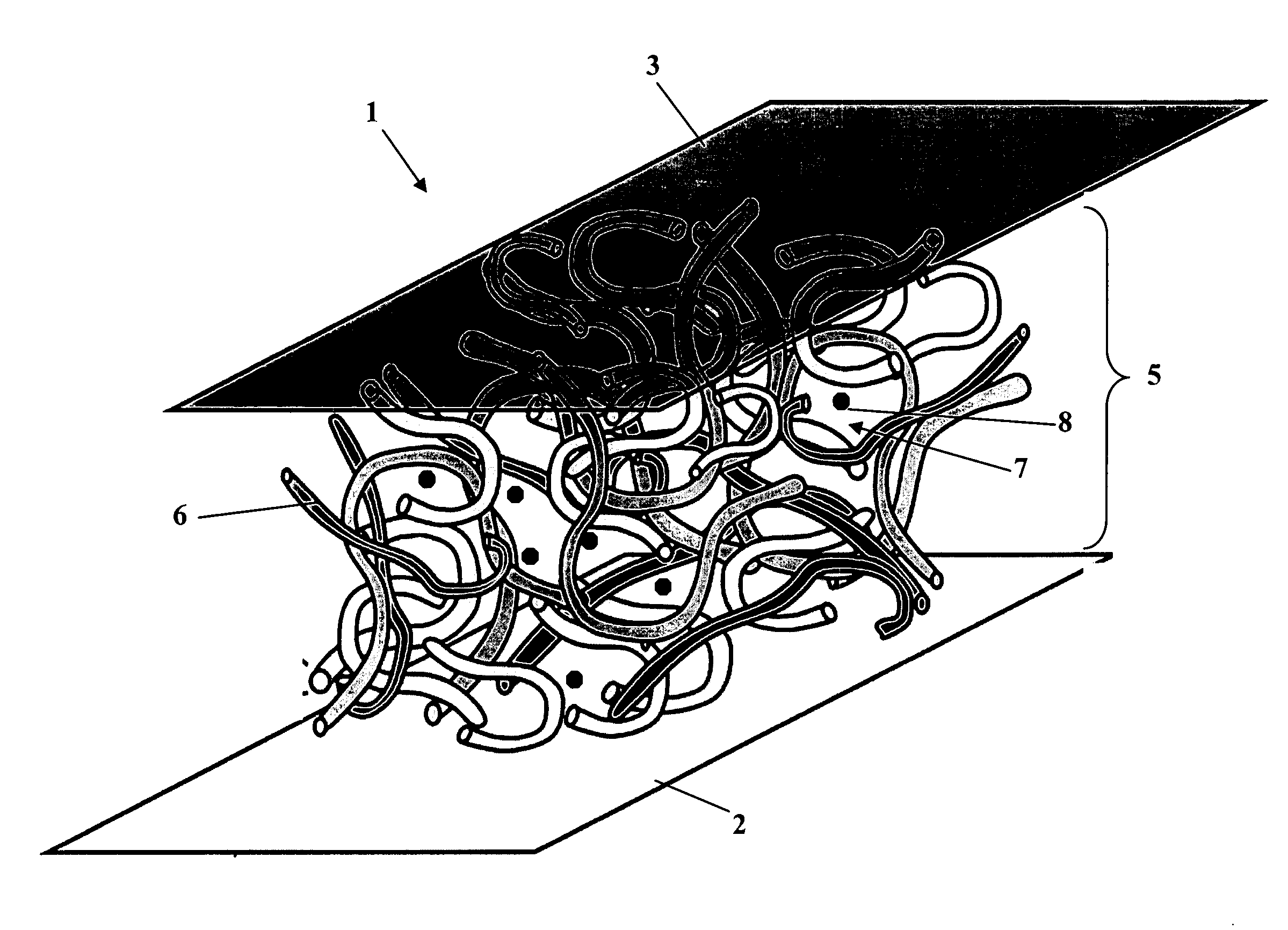
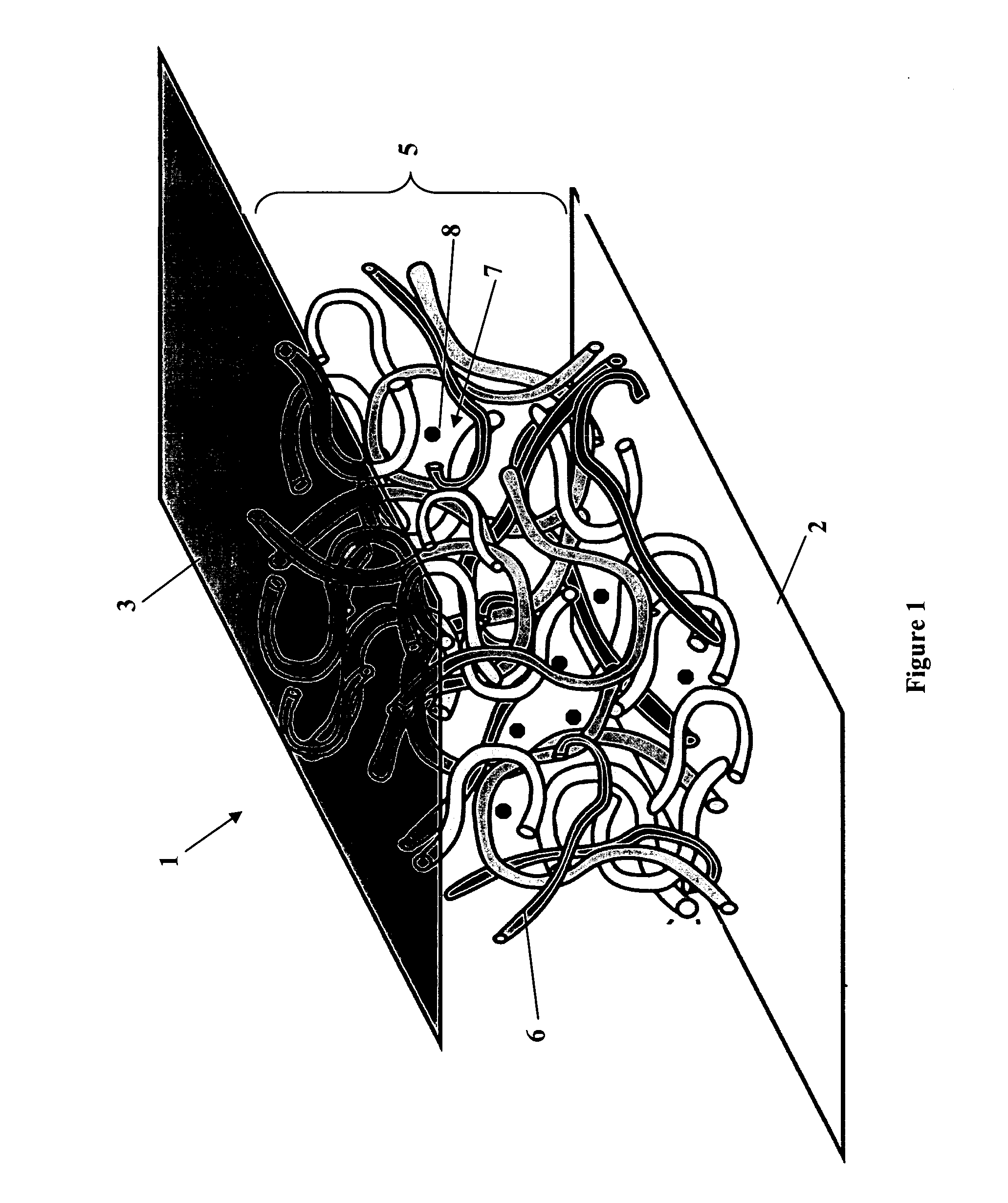
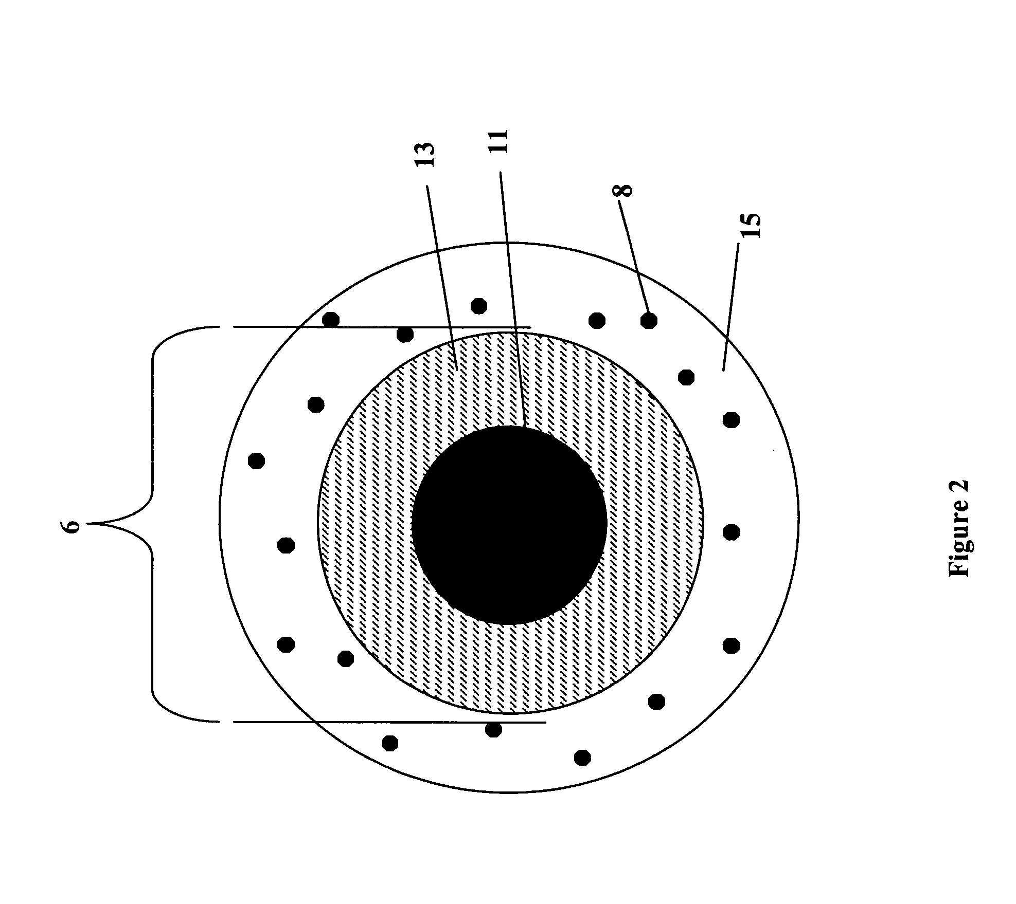
[0047]FIG. 10 shows an embodiment of a three-dimensional battery device 76 including an anode current collector 80, a cathode current collector 84, and a network of fibers 88. The anode current collector 80 includes copper. The cathode current collector 84 includes nickel. The network of fibers 88 can be formed from LiNi0.7Co0.302 fibers. The fibers can be deposited by electrospinning fibers on the cathode current collector 84. The sol-gel precursor solution can include metal acetates, poly(vinyl acetate) binder, and water. The network of fibers 88 can be heat treated at 600° C. to yield a continuous fiber network in direct contact with the cathode current collector 84. PPD can be added coat the fibers by electrochemical polymerization to form the separator / electrolyte. Graphite anode nanoparticles (not shown) can be infiltrated into pores defined in the fiber n...


PUM

PropertyMeasurementUnit
Temperatureaaaaaaaaaa
Thicknessaaaaaaaaaa

Abstract

A battery device includes a cathode current collector and an anode current collector. A fibrous electrode forms a structure defining a plurality of pores. A first portion of the fibrous electrode is in contact with a current collector. An electrolytic polymer is electrodeposited on the fibrous electrode to provide substantial uniform coverage of fibers forming the fibrous electrode. A plurality of electrode particles are disposed within the plurality of pores and separated from the fibrous electrode by the electrolytic polymer.

Description

GOVERNMENT RIGHTS[0001]This invention was made with government support under Contract No. N66001-04-C-8025 and Contract No. N00164-03-C-6030, both awarded by the United States Navy. The government may have certain rights in the invention.FIELD OF THE INVENTION[0002]In general, the invention relates to three-dimensional batteries. In particular, the invention relates to a battery device with interpenetrating, co-continuous electrodes including fibers and / or a plurality of particles that function as an electroactive material.BACKGROUND OF THE INVENTION[0003]The worldwide demand for portable electronic devices in the past decade have had an enormous impact on the development of portable energy storage devices. Batteries in which lithium ions shuttle between a cathode and an anode have emerged as the power source of choice for the high performance rechargeable battery market. The thick metal plates of traditional batteries have given way to lithium ion cells, which are lighter and more ...

Claims


Application Information

Patent Timeline
IPC IPC(8): H01M4/60B32B37/12H01M4/00H01M4/96H01M4/38H01M4/52H01M4/02H01M4/131H01M4/1393H01M4/48H01M4/485H01M4/525H01M10/0525H01M10/0565H01M10/36
CPCH01M4/02H01M4/131H01M4/1393H01M4/485H01M4/525Y10T29/49115H01M10/0565H01M2004/021H01M2300/0082Y02E60/122Y10S977/948H01M10/0525Y02E60/10Y02P70/50
Inventor WHITE, KEVINHORN, QUINNSALLEY, EDWARDLENNHOFF, JOHN
Owner PHYSICAL SCI
Learn More