Mitigation of photodamage in analytical reactions
a technology of photodamage and analytical reactions, applied in the direction of instruments, transferases, peptide/protein ingredients, etc., can solve the problems of damage to such reactants, e.g., proteins, enzymes, substrates, and the detrimental effect of such photodamage on the operation of the given analysis
- Summary
- Abstract
- Description
- Claims
- Application Information
AI Technical Summary
Benefits of technology
Problems solved by technology
Method used
Image
Examples
example 1
Photodamage and Mitigation in Bulk Reaction Volumes
[0059]In a first assay, synthesis reaction mixtures contained a modified (φ29 DNA polymerase, 300 nM DNA template, three native nucleoside triphosphates (at 10 μM each) and a fluorescent dye labeled nucleoside polyphosphate (at 10 μM) in synthesis buffer (50 mM Tris-HCl, pH 7.5, 75 mM KCL, 20 mM (NH4)2SO4, 10 mM BME, 0.7 mM MnCl2). Each of the reactions were carried out at room temperature (22° C.) for the desired illumination period, ranging from 1 minute to one hour.
[0060]The experiment included two sets each of three different reaction mixtures: (1) a synthesis reaction using only native, e.g., unlabeled nucleoside triphosphates; (2) a synthesis reaction including two native nucleoside triphosphates, an Alexa 488 labeled dCTP analog, and an Alexa 568 labeled dTTP; and (3) a synthesis reaction including two native nucleoside triphosphates, an Alexa 488 labeled dC4P analog (tetraphosphate), and an Alexa 568 labeled dT4P. Each diffe...
example 2
Photodamage and Mitigation in Surface Immobilized Enzyme Systems
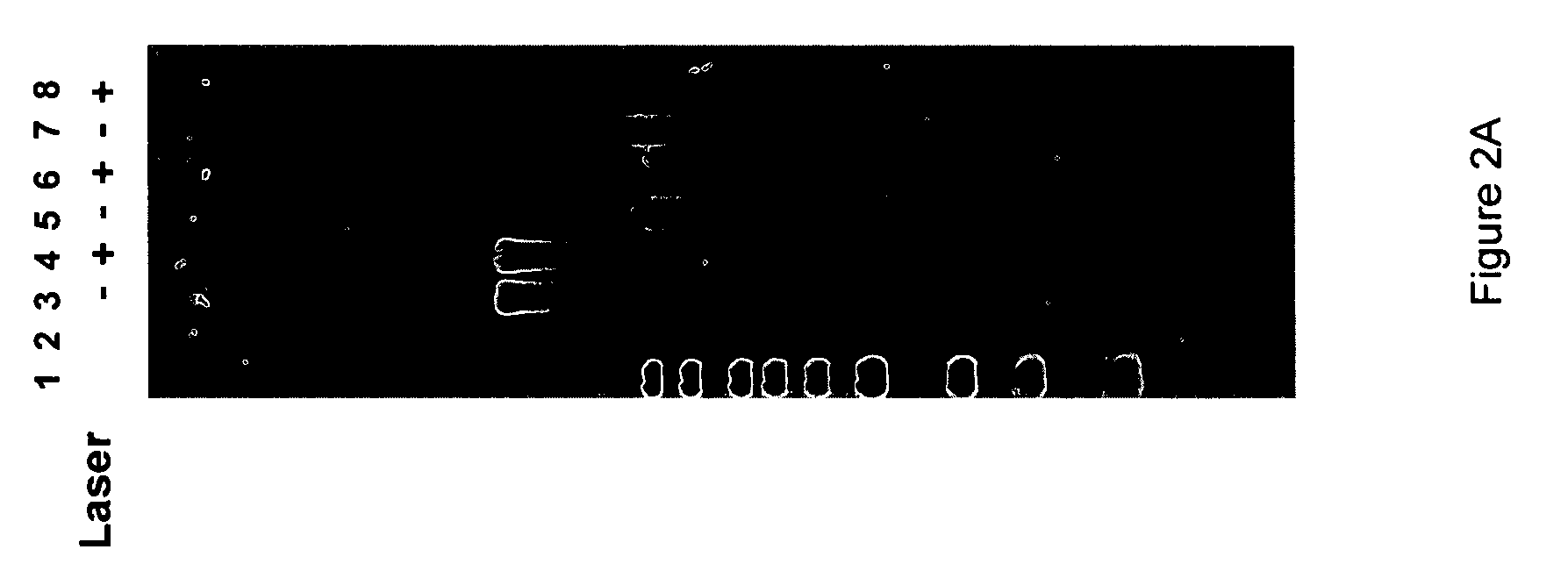
[0065]Next, a GST-tagged φ29 polymerase was coated on the surface of a fused silica microscope slide, by depositing the polymerase over the slide and incubating the surface for 15 minutes on ice. Template dependent synthesis of DNA was carried out on the surface using native nucleotides and 10 μM Alexa488-labeled-dC4P and Alexa568-labeled-dT4P, while illuminating a small semi-circular shaped laser spot on the slide. The only reducing agent present in the mixture was 10 mM βME. The slides were exposed to laser illumination at 488 nm (1.1 mW) and 568 nm (1.8 mW) with different positions being illuminated for 1 minute and for 5 minutes. Following illumination, synthesis was allowed to continue for 60 minutes using only native nucleotides. The slides were stained for the presence of synthesized DNA using Sybr-gold. Images of the illuminated slides after 1 minute and 5 minutes are shown in FIG. 3A. As can be seen, the semici...
example 3
Photodamage and Mitigation on Nanostructured Reactive Surfaces
[0074]A similar set of experiments to those described above were performed using DNA polymerase immobilized within zero mode waveguides in an array of waveguides. As above, the first experiment was designed to identify whether laser illumination caused damage to immobilized polymerase enzymes on nanostructured surfaces. The surfaces included ZMW arrays in which the polymerase enzyme was adsorbed to the surface. DNA synthesis using dye labeled nucleoside tetraphosphates (Alexa488dC4P and Alexa568dT4P) was carried out with and without laser illumination (at 488 and 568 nm) and the resulting product was again stained with Sybr® Gold. Images of the arrays are shown in FIG. 4A. The illumination profile is shown in the first panel (far left), while the image of the stained DNA product in the illuminated synthesis is shown in the adjacent panel (middle left). As can be seen, a negative image is apparent in the illuminated region...
PUM
 Abstract
Description
Claims
Application Information
 - R&D
- Intellectual Property
- Life Sciences
- Materials
- Tech Scout
- Unparalleled Data Quality
- Higher Quality Content
- 60% Fewer Hallucinations
Browse by: Latest US Patents, China's latest patents, Technical Efficacy Thesaurus, Application Domain, Technology Topic, Popular Technical Reports.
© 2025 PatSnap. All rights reserved.Legal|Privacy policy|Modern Slavery Act Transparency Statement|Sitemap|About US| Contact US: help@patsnap.com


