Gas purge method and apparatus

a gas purge and gas technology, applied in the field of gas purge methods and apparatuses, can solve the problems of wasting purging gas, absorbing more time, and insufficient use of clean rooms

Inactive Publication Date: 2008-07-24
RICOR
View PDF18 Cites 9 Cited by
  • Summary
  • Abstract
  • Description
  • Claims
  • Application Information

AI Technical Summary

Benefits of technology

[0010]It is therefore the object of the present invention to obviate the disadvantages of prior art devices and to provid...

Problems solved by technology

The use of clean rooms is often inadequate because the clean air therein contains oxygen water vapor, other hazardous gasses and of course airborne particles.
This lack le...

Method used


Image

  • Gas purge method and apparatus
  • Gas purge method and apparatus
  • Gas purge method and apparatus

Examples


embodiment 54

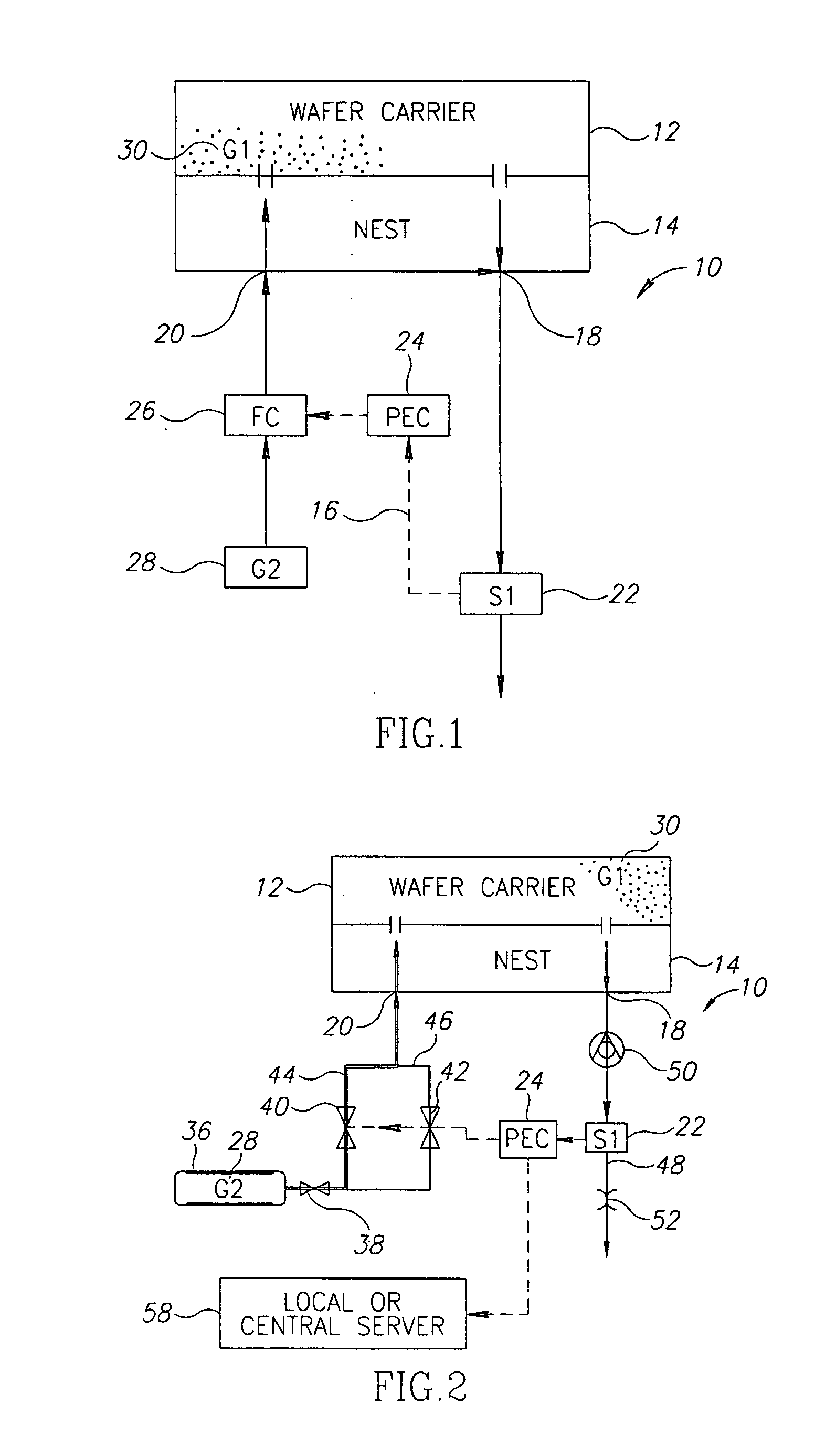
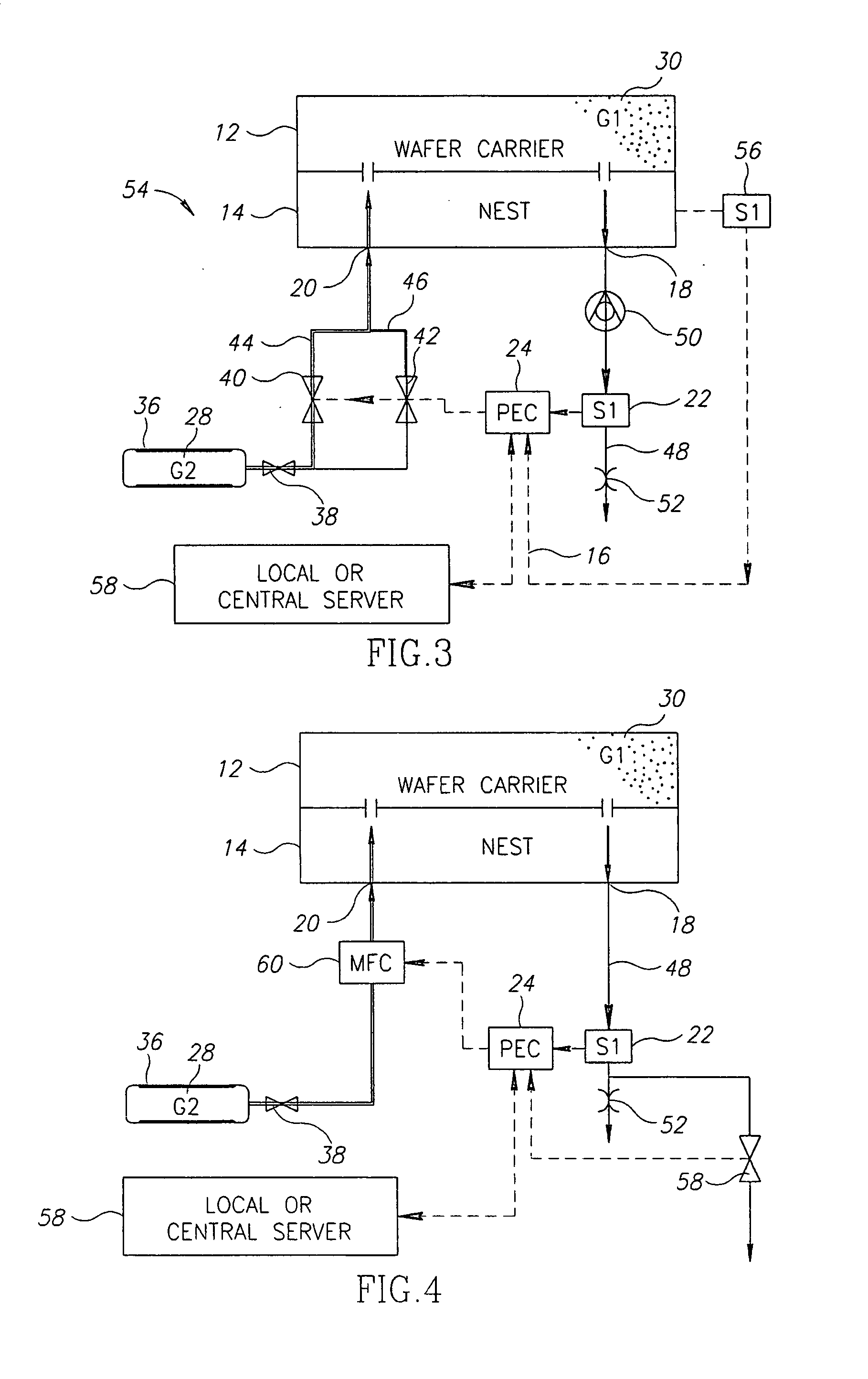
[0058]FIG. 4 illustrates a further embodiment 54. A mass flow controller (MFC) 60 is connected to the nest inlet port 20 instead of the valves 40, 42 which are not needed. Also seem is a third valve 58 connected to the nest outlet, which can be opened at the beginning of the purge process to reduce purge time. The valve is however closed by the PEC 24 a few seconds after starting to prevent excessive loss of the second gas 28.

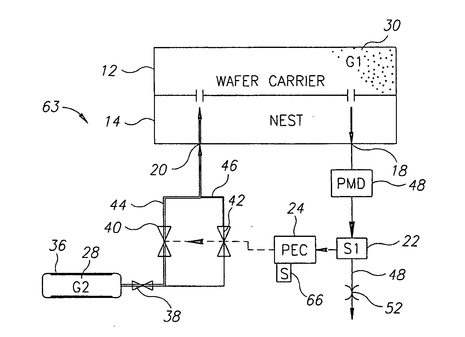
[0059]Seen in FIG. 5 is an apparatus 63 optionally provided with a particle measurement device 64 in fluid communication with the nest outlet port 18. The device 64 is useful in combination with a Quality Assurance program. If particles density of a size larger than a preset limit are detected or a specific material composition is detected an alarm will be activated and a warning message will be sent to the factory host computer and appear on a screen 66 electrically connected to the PEC 24.

embodiment 68

[0060]Referring now to FIG. 6, there is depicted a practical embodiment 68, for reference only. No additional novelty is intended to be shown in this figure.

[0061]With regard to the method of the invention, reference will be made to the apparatus described and components thereof, particularly with reference to FIG. 3.

[0062]A method, particularly useful in the production of semiconductors, for automatically and economically purging a first gas or mixture from a closed container or nest, said method having the following steps:

[0063]step a: providing equipment including

[0064]a first sensor 22 in fluid communication with the outlet of a vessel 48 containing a first gas 30 to be removed;

[0065]a source 36 of a second compressed inert gas 28 suitable for purging said first gas 30;

[0066]at least one remotely controllable inlet valve 40 disposed between said source of said compressed second gas 28 and the inlet 20 of said container 12, 14;

[0067]a flow restrictor 52 disposed in said outlet of...


PUM


Abstract

The present invention relates to the removal of a gas or of a gas mixture from a closed container.
More particularly, the invention provides a method and apparatus particularly useful in the production of semiconductors, for automatically and economically purging a first gas or gas mixture from a closed container.
The present invention achieves the above object by providing a method and an apparatus, particularly useful in the production of semiconductors, for automatically and economically purging a first gas or mixture from a closed container, said method having the following steps:
  • step a: providing equipment including
  • a first sensor in fluid communication with the outlet of said container;
  • a source of a second compressed gas suitable for purging said first gas;
  • at least one remotely controllable inlet valve disposed between said source of said compressed gas and the inlet of said container;
  • a flow restrictor disposed in said outlet of said container;
  • an electronic controller connected to and able to receive data from said first sensor and able to control at least one said inlet valve according to a predetermined program relating valve opening to time and to data from said first sensor;
  • step b: sending a start signal, which optionally may be generated automatically, to said electronic controller;
  • step c: start releasing said second gas into said container, the flow rate being controlled by said electronic controller;
  • step d: measuring a parameter of interest by means of a first sensor at the outlet of said container and sending data relating to said parameter to said controller; and
  • step e: adjusting inlet flow in relation to purging progress.

Description

CROSS REFERENCE TO RELATED APPLICATIONS[0001]This application claims priority from Israeli Patent Application Number 180875, filed on Jan. 22, 2007, which is incorporated in its entirety herein by reference.FIELD OF THE INVENTION[0002]The present invention relates to the removal of a gas or of a gas mixture from a closed container.[0003]More particularly, the invention provides a method and apparatus particularly useful in the production of semiconductors, for automatically and economically purging a first gas or gas mixture from a closed container.BACKGROUND OF THE INVENTION[0004]Valuable articles or articles that are irreplaceable but which are to be preserved, for example old documents or exceptionally valuable paintings or a world standard item such as a kilogram weight are best preserved in an inert atmosphere such as in a vacuum or in an inert gas such as Nitrogen, carbon dioxide or helium. In particular during the manufacture of semi-conductors, the wafers being processed mus...

Claims


Application Information

Patent Timeline
IPC IPC(8): G06F19/00
CPCH01L21/67393H01L21/67017
Inventor HAREL, EREZGARDI, EYAL
Owner RICOR
Why Eureka
Try Eureka