
Method for treating a thermally loaded component

a technology for thermally loaded components and components, applied in the direction of machines/engines, mechanical equipment, chemistry apparatus and processes, etc., can solve the problems of increasing the cost of chemical processes, increasing the cost of finishing machining, and local defects, so as to increase the efficiency of the removal process and influence.

Inactive Publication Date: 2008-07-31
ALSTOM TECH LTD
View PDF38 Cites 11 Cited by
  • Summary
  • Abstract
  • Description
  • Claims
  • Application Information

AI Technical Summary

Benefits of technology

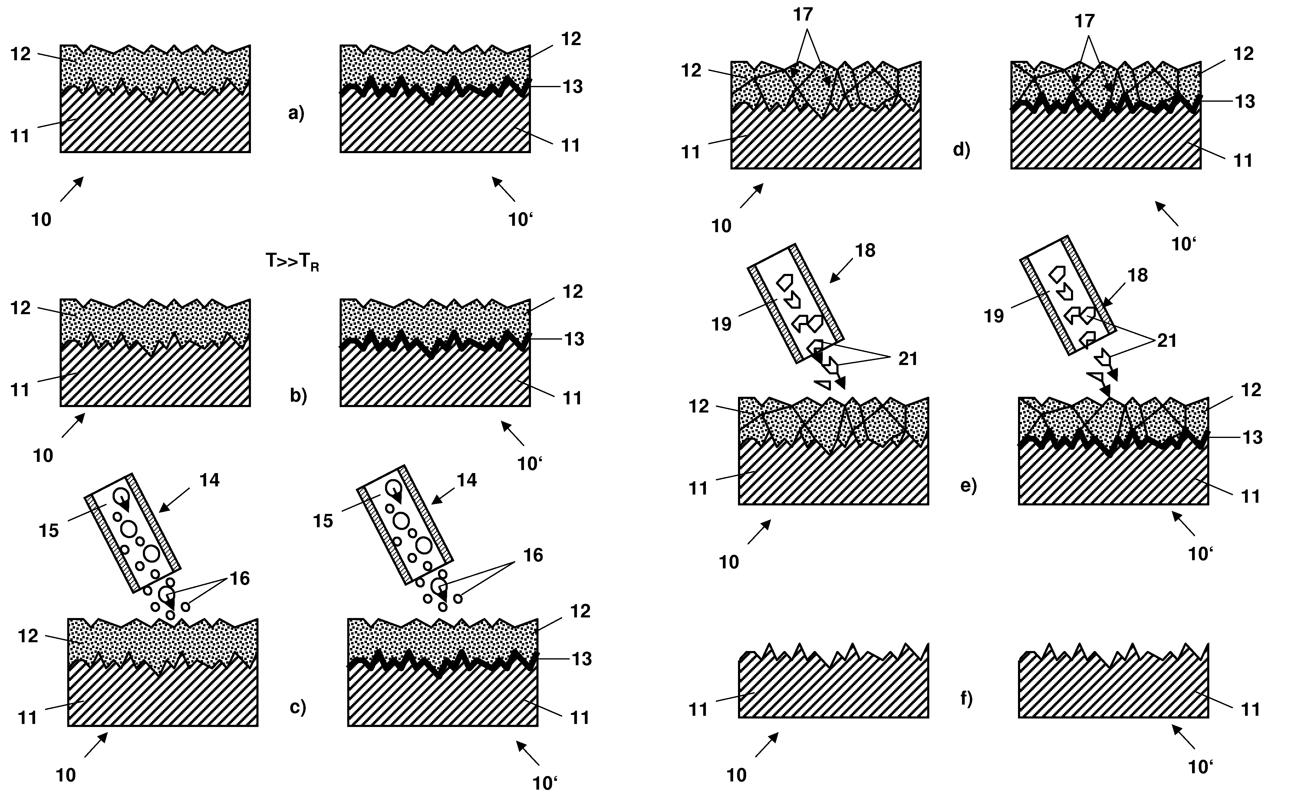
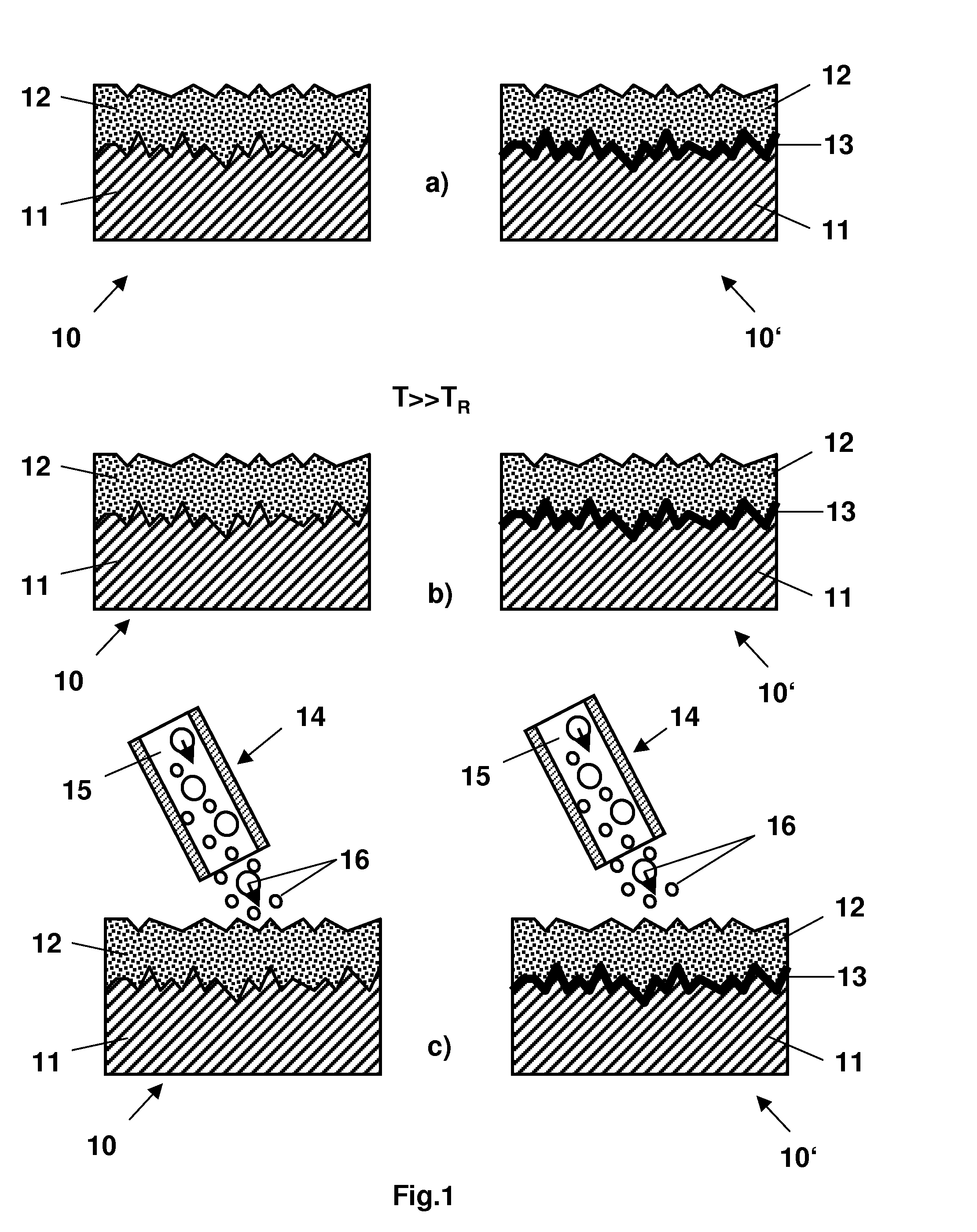
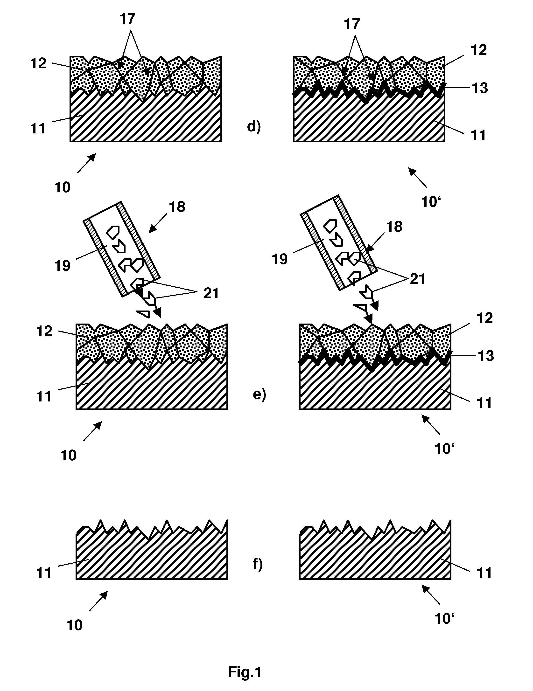
[0010]The present invention provides a method for treating a thermally loaded component having a metallic substrate areally coated with a protective coating on a at least a portion of an outer side. The method includes removing the protective coating from the substrate using a dry ice blasting process, wherein, before the application of the dry ice blasting process the protective coating is first of all predamaged in a first step in such a way that the predamaging leads to an increase of the efficiency of the removal process.
[0011]The invention thus provides a two-stage treatment process, in which before the application of the dry ice blasting process the protective coating is first of all purposefully predamaged in a first step. By means of the purposeful predamaging of the coating which is to be removed, this can be more effectively, i.e. in shorter time, completely removed in the subsequent dry ice blasting process and without greater influence upon possible metal coatings which lie beneath it.

Problems solved by technology

When applying these thermal barrier coatings, local defects can occur, which are not acceptable with regard to later application, or which have to be removed for other reasons.
This chemical process is very burdensome and costly, and requires greater finish-machining.
Also, it is not possible to selectively remove only areas of the protective coating in order to finish used components, for example, for renewed application.
With this type of coating removal, however, the complete removal of the coating on the one hand, and the least possible influencing of the metallic coatings (either the metal substrate as such, or the metallic bonding layer or adhesion mediating coating which lies above it) which lies beneath the coating which is to be removed on the other hand, is problematic.
Previous processes suffer from low efficiency or very long treatment durations.

Method used


Image

  • Method for treating a thermally loaded component
  • Method for treating a thermally loaded component
  • Method for treating a thermally loaded component

Examples


Embodiment Construction

[0024]The present invention refers to a method for removing a brittle coating system (protective coating 12 in FIG. 1(a) or FIG. 2(a)) from a metallic surface (a substrate 11 in FIG. 1(a) or 2(a)). The coating system which is to be removed is typically a ceramic system, i.e. a thermal barrier coating such as yttrium-stabilized zirconium oxide (ZrO27% Y2O3 or the like) or comprises a coating consisting of the system La-oxide, or ZrO with additives from the range of rare earths (Er, Yb) and P and Gd. The thermal barrier coating can be applied by means of thermal spraying processes, which use powder or solutions / suspensions as a carrier of the coating material, and also can also be applied by means of other physical processes like EB-PVD.

[0025]In the case of used components, which were already subjected to a longer thermal loading in the presence of oxygen, a thermally grown oxide coating (13 in FIG. 1(a) or 2(a), right-hand column), may have been formed beneath the upper protective co...


PUM

PropertyMeasurementUnit
Temperatureaaaaaaaaaa
Diameteraaaaaaaaaa

Abstract

A method for treating a thermally loaded component having a metallic substrate and at least partially coated on an outer side with a protective coating, is provided. The method includes the step of predamaging the protective coating before removing the protective coating from the substrate using dry ice blasting. The predamaging is performed so as to lead to an increase of efficiency of the removal process.

Description

[0001]Priority is claimed to Swiss Patent Application No. CH 00103 / 07, filed Jan. 23, 2007, the entire disclosure of which is incorporated by reference.[0002]The present invention relates generally to the field of thermal machine, and more particularly to a method for treating a thermally loaded component having a metallic substrate and a protective coating on at least a portion of an outer side.BACKGROUND[0003]Thermally loaded components of gas turbines, such as stator blades or rotor blades or elements of the associated combustion chamber, which on account of the high operating temperatures are produced from Ni-based alloys, are frequently coated on the surface with a ceramic thermal barrier coating (TBC). When applying these thermal barrier coatings, local defects can occur, which are not acceptable with regard to later application, or which have to be removed for other reasons. If such local defects occur, the whole thermal barrier coating, inclusive of the bonding layer which l...

Claims


Application Information

Patent Timeline
IPC IPC(8): C23G1/00C25F5/00
CPCB24C1/003B24C1/086F01D5/288F01D5/005F01D5/286B24C1/10
Inventor DUDA, THOMASENGL, LARS
Owner ALSTOM TECH LTD
Learn More