Light-emitting material, scintillator containing the light-emitting material, x-ray detector equipped with the scintillator, image display device using the light-emitting material, and light source using the light-emitting material

Active Publication Date: 2008-07-31
KK TOSHIBA
View PDF7 Cites 15 Cited by
  • Summary
  • Abstract
  • Description
  • Claims
  • Application Information

AI Technical Summary

Benefits of technology

[0015]The present invention has been made in view of these circumstances, and an object thereof is to provide, in addition to a light-emitting material having a short decay time of 10 μs or less and an emission wavelength of 650 nm or longer, a scintillator composed of the light-emitting material, an X-ray detector equipped with the scintillator, a light-emitting material which emits light having a higher luminance than light emitted from a phosphor represented by ZnS and an excellent emission color under excitation by a high energy-density electron beam and which can widen a color reproduction range, an image display device using the light-emitting material, and a light source using the light-emitting material.

Problems solved by technology

However, the peak emission wavelengths of these scintillators are 415 nm, 470 nm, and 510 nm, respectively, which are not sufficiently long from the viewpoint of matching with a silicon photodiode.
In addition, the ceramic scintillator composed of (Y,Gd)2O3:Eu has a decay time of 1 ms or longer, and is therefore not suitable for use in fast-response X-ray detectors.
In this list, light-emitting materials having an emission wavelength of 650 nm or longer are limited to chemically-unstable materials likely to react with water such as CaO and CaS and nitrides difficult to be synthesized.
However, in a case where these phosphors are excited by a high energy-density electron beam, their luminous efficiency is lowered due to saturation.
However, there is no known blue light-emitting phosphor which emits light having a higher luminance than light emitted from a phosphor represented by ZnS and an excellent emission color under excitation by a high energy-density electron beam.
As has been described above, any conventional scintillators do not satisfy both the requirements of a short decay time and a long emission wavelength.
Further, as has been described above, the properties of the well-known light-emitting materials are not yet sufficient for many purposes of use, and therefore the advent of novel phosphors such as a blue light-emitting phosphor which emits light having a higher luminance than light emitted from a phosphor represented by ZnS and an excellent emission color under excitation by a high energy-density electron beam, and a white phosphor capable of realizing a backlight light source which can widen the color reproduction range of a liquid crystal display when used together with red, green, and blue color filters has been awaited.

Method used


Image

  • Light-emitting material, scintillator containing the light-emitting material, x-ray detector equipped with the scintillator, image display device using the light-emitting material, and light source using the light-emitting material
  • Light-emitting material, scintillator containing the light-emitting material, x-ray detector equipped with the scintillator, image display device using the light-emitting material, and light source using the light-emitting material
  • Light-emitting material, scintillator containing the light-emitting material, x-ray detector equipped with the scintillator, image display device using the light-emitting material, and light source using the light-emitting material

Examples


first embodiment

[0043]A first embodiment of the present invention will be described.

[0044]A light-emitting material according to the first embodiment of the present invention has a composition represented by NaYS2:Eu. The light-emitting material is obtained by adding Eu to a matrix represented by NaYS2. As far as the present inventors know, a phosphor represented by this compositional formula has not yet been known. In addition, the present inventors have found that this phosphor exhibits unique light emission different from that of a Eu-activated phosphor usually used.

[0045]In a case where Eu is added to a matrix containing a rare-earth element such as Y, Eu usually exists as Eu3+, and a line emission spectrum with a peak at about 610 nm to 630 nm unique to Eu3+ is shown.

[0046]On the other hand, it is known that in a case where Eu is added to a matrix containing an alkaline-earth metal such as Ba or Sr, Eu often exists as Eu2+, and a band emission spectrum unique to Eu2+ is shown.

[0047]The present...

second embodiment

[0065]The light-emitting material according to the second embodiment of the present invention can be produced in the following manner.

[0066]First, 20.49 g of Na2S, 102.4 g of Gd2S3, and 0.264 g of Eu2O3 as raw materials were weighed, and were then fired in a hydrogen sulfide atmosphere at 1,000° C. for 3 hours to obtain a light-emitting material according to the second embodiment of the present invention. The obtained light-emitting material also had a pink color. The light-emitting material according to the second embodiment of the present invention was excited by a pulsed electron beam having an acceleration voltage of 10 kV to evaluate the decay characteristics of the light-emitting material. As a result, the decay time of the light-emitting material, during which the emission intensity thereof was reduced to 10%, was 7 μs. From the result, it was confirmed that the light-emitting material had a sufficiently short decay time of 10 μs or less.

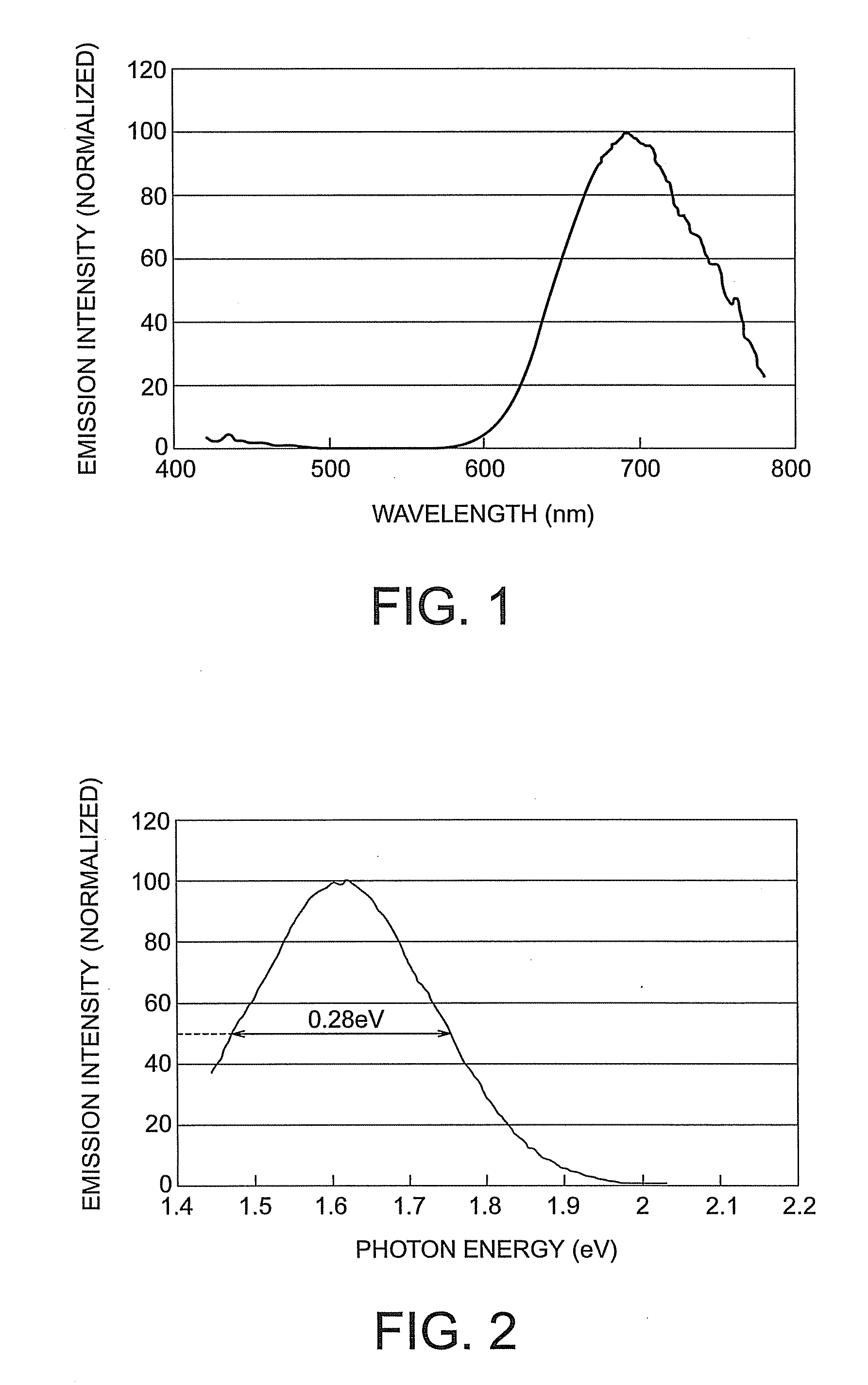
[0067]Further, the emission spectrum o...

third embodiment

[0071]A light-emitting material according to a third embodiment of the present invention has a matrix having a composition represented by ARS2, where A represents at least one element selected from Na, K, Rb, and Cs, and R represents at least one element selected from Y, La, Gd, and Lu. Examples of an activator to be used include rare-earth elements such as Ce, Pr, Eu, and Tb, transition metals such as Mn and Cu, and In, Sn, Sb, and Bi which become an ion having two s electrons and emit light by transition as in the case of Tl+. It is to be noted that the activator refers to an element doped so as to be a luminescent center. It is generally known that there is an optimum concentration of the activator, and in either case where the amount of the activator is too much or too little, emission characteristics such as luminous efficiency are deteriorated. The optimum concentration varies depending on the kind of matrix used and the kind of activator ion used, but often lies in the range ...


PUM


Abstract

It is made possible to provide a light-emitting material having a short decay time of 10 μs or less and an emission wavelength of 650 nm or longer. A light-emitting material includes a material having a composition represented by ARS2:Eu, wherein A represents at least one element selected from Na, K, Rb, and Cs, and R represents at least one element selected from Y, La, Gd, and Lu.

Description

CROSS-REFERENCE TO RELATED APPLICATION[0001]This application is based upon and claims the benefit of priority from prior Japanese Patent Applications No. 2007-19274 and No. 2007-196135 filed on Jan. 30, 2007 and Jul. 27, 2007 in Japan, the entire contents of which are incorporated herein by reference.BACKGROUND OF THE INVENTION[0002]1. Field of the Invention[0003]The present invention relates to a light-emitting material, a scintillator containing the light-emitting material, an x-ray detector equipped with the scintillator, an image display device using the light-emitting material, and a light source using the light-emitting material.[0004]2. Related Art[0005]In recent years, there has been a growing demand for a fast-response and higher-sensitivity X-ray detector as the speed of X-ray CT (Computed Tomography) has become faster and the definition of X-ray CT has become higher. Currently, an X-ray detector mainly used is composed of a scintillator for converting X-ray into light and...

Claims


Application Information

Patent Timeline
IPC IPC(8): G01T1/20C01F17/00H01J1/62
CPCC01F17/0012C01P2002/52C01P2002/84C01P2006/60C09K11/7703H01L2224/13C09K11/7786H01L27/14663H01L31/02322H01L33/502H01L2224/73265C09K11/7768C01F17/30H01L2224/0554H01L2224/05568H01L2224/05573H01L2924/00014H01L2224/05599H01L2224/05099H01L2224/0555H01L2224/0556
Inventor MATSUDA, NAOTOSHI
Owner KK TOSHIBA
Why Eureka
Try Eureka