Control apparatus of servo motor

a technology of servo motor and control apparatus, which is applied in the direction of electric programme control, program control, instruments, etc., can solve the problems of affecting the work efficiency the precision of the work of the machine tool etc. is liable to fall, and the precision of the control apparatus is prone to fall, so as to achieve superior control precision and reduce mechanical resistance

Active Publication Date: 2008-07-31
FANUC LTD
View PDF11 Cites 17 Cited by
  • Summary
  • Abstract
  • Description
  • Claims
  • Application Information

AI Technical Summary

Benefits of technology

[0025]According to the control apparatus of a servo motor of the present invention, the mechanical system comprised of a servo motor and a driven part driven by this servo motor is suppressed in mechanical resistance due to low frequency vibration and superior in control precision.

Problems solved by technology

In this case, in the control apparatus of Japanese Patent No. 2504307 or Japanese Patent Publication (A) No. 2004-272883, either the vibration due to mechanical resonance cannot be sufficiently suppressed or the precision of the position to be controlled ends up falling, so the precision of work of the machine tool etc. is liable to fall.
Further, in a machine tool, when applying a filter to the feed shaft where low frequency mechanical resonance occurs so as to suppress such vibration, the work results may deteriorate due to the effect of the control delay of the operating shafts at locations of sharp angle operation and locations of high acceleration.
In this way, if simply filtering the position command or speed command, sometimes speed commands required for acceleration or deceleration of the motor are not sufficiently output.
As a result, the work precision of machine tools etc. is liable to deteriorate.
Further, if lowering the frequency band of the gain of the transfer function in the control apparatus of a servo motor below the frequency of the mechanical resonance to avoid this low frequency vibration, the dynamic characteristics of the mechanical system end up falling.

Method used


Image

  • Control apparatus of servo motor
  • Control apparatus of servo motor
  • Control apparatus of servo motor

Examples


first embodiment

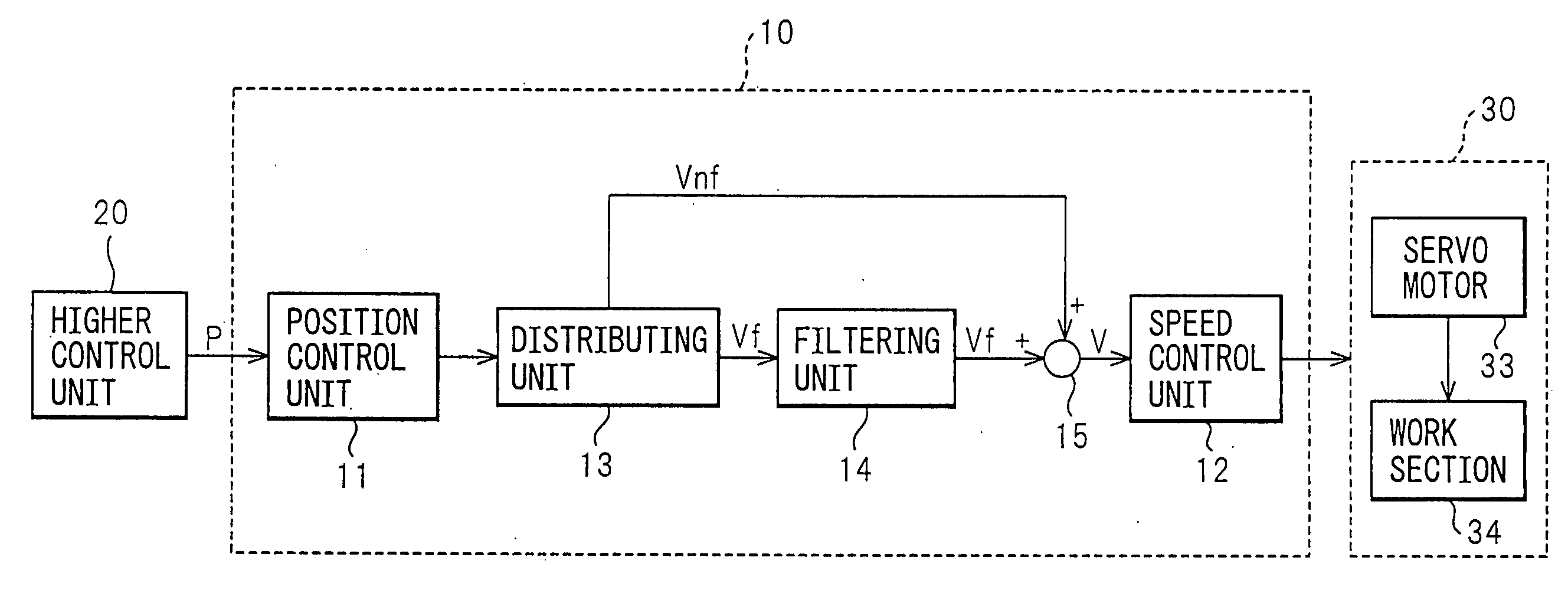
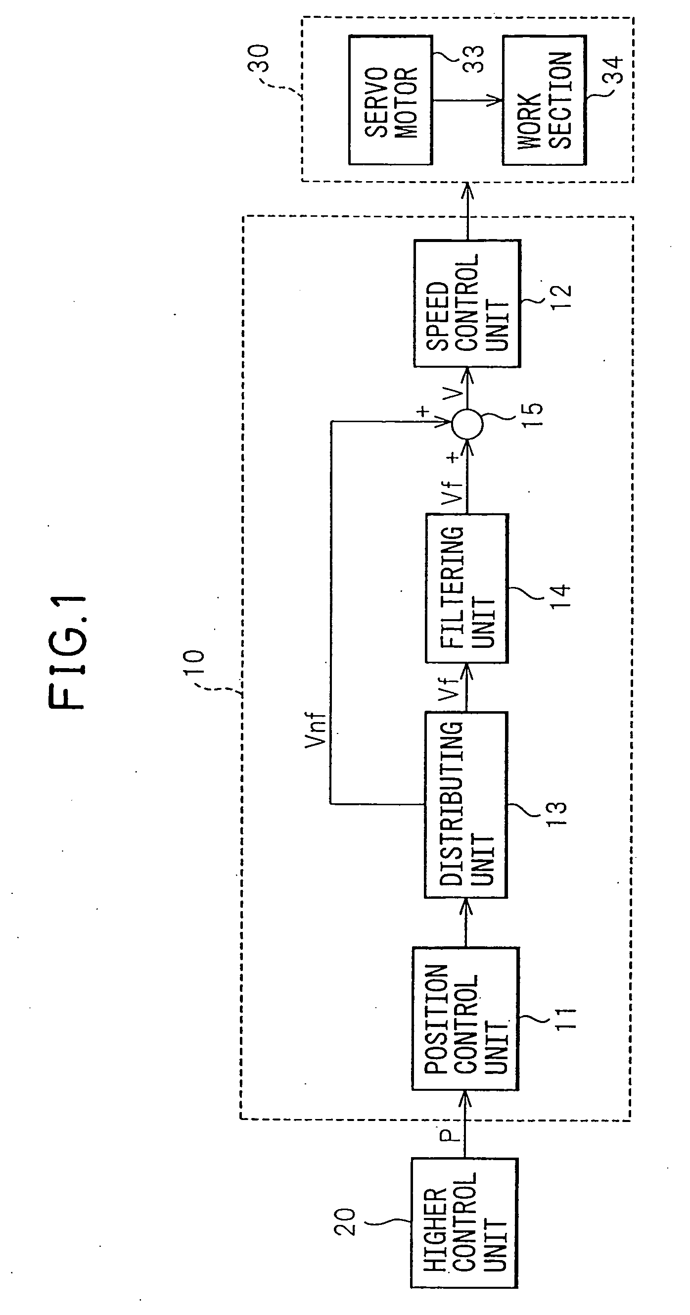
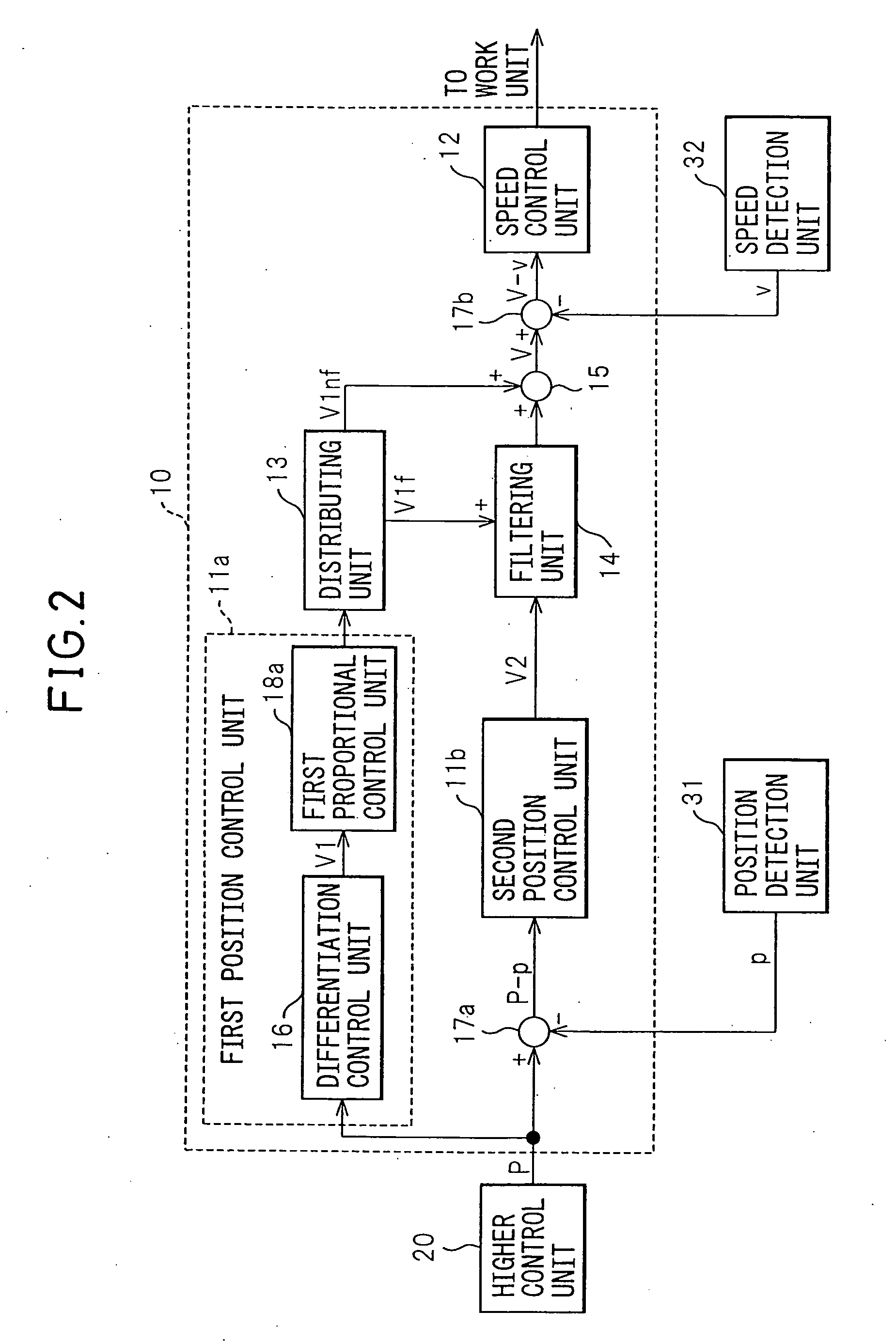
[0056]The control apparatus 10 of a servo motor of a first embodiment of the present invention (hereinafter also referred to simply as the “apparatus 10”), as shown in FIGS. 2 to 4, has the position control unit 11 controlling the position of the servo motor 33 and the speed control unit 12 controlling the speed of the servo motor 33.

[0057]Further, the apparatus 10 has the higher control unit 20 outputting a position command P and the position detection unit 31 detecting the position of the servo motor 33 and outputting the position detection value p. The first position control unit 11a to which the position command P is input outputs the first speed command V1 found in accordance with the differential value of the position command P to the distributing unit 13. Further, the second position control unit 11b to which the positional difference P-p obtained from the position command P and the position detection value p is input outputs a second speed command V2.

[0058]Further, the adder...

second embodiment

[0093]The control apparatus 10 of a servo motor of a preferred second embodiment of the present invention will be explained below with reference to FIG. 7. The difference from the above-mentioned first embodiment is that the control apparatus 10 of a servo motor of the present embodiment (hereinafter also referred to simply as the “apparatus 10”) has a changing unit 19a for changing the third processing constant k.

[0094]The changing unit 19a changes the value of the third processing constant k at the distributing unit 13 in accordance with the operation of the working unit 30 and the position command P etc. and thereby changes the ratio of application of the filter to the first speed command V1. Due to this, vibration due to the mechanical resonance of the working unit 30 is suppressed, and the precision of positional control of the servo motor 33 is enhanced.

[0095]Specifically, the changing unit 19a of the apparatus 10 changes the value of the third processing constant k according ...

third embodiment

[0118]Next, the control apparatus 10 of a servo motor of a preferred third embodiment of the present invention will be explained below with reference to FIG. 10. The point of difference from the above-mentioned second embodiment is that the changing unit 19c of the control apparatus 10 of a servo motor of the present embodiment (hereinafter also referred to simply as the “apparatus 10”) changes the third processing constant k depending on the feed type of the work section 34 of the working unit 30.

[0119]In the apparatus 10, the third processing constant k is switched by the changing unit 19c when the position command P instructs working by the work section 34 of the working unit 30 and when it instructs only movement of the work section 34 of the working unit 30 without being accompanied with working.

[0120]The position command preparing unit 21 of the higher control unit 20, as shown in FIG. 10, outputs the feed type of the work section 34 of the working unit 30 to the changing unit...


PUM


Abstract

The control apparatus 10 of a servo motor of the present invention has a position control unit 11 controlling the position of a servo motor 33, a speed control unit 12 controlling a speed of the servo motor 33, a distributing unit 13 dividing the speed command output by the position control unit 11 into a filtered part Vf which is filtered to suppress vibration and a nonfiltered part Vnf, a filtering unit 14 receiving as input the filtered part Vf and filtering and outputting the filtered part Vf, and an adder unit 15 adding the filtered part Vf filtered by the filtering unit 14 and the nonfiltered part Vnf and outputting the result to the speed control unit 12.

Description

[0001]The applicant claims the right to priority based on Japanese Patent Application No. 2007-017824, filed on Jan. 29, 2007. The entire content of Japanese Patent Application No. 2007-017824 is hereby incorporated by reference.FIELD OF THE INVENTION[0002]The present invention relates to a control apparatus of a servo motor, more particularly relates to a control apparatus of a servo motor suppressing vibration due to resonance in a mechanical system comprised of a servo motor and a driven part driven by this servo motor.BACKGROUND OF THE INVENTION[0003]In the past, control apparatuses of servo motors have been used in machine tools and industrial machines. In particular, the control apparatus of a servo motor using feedback control performs control so that the differences between the position, speed, current, and other command values and actual values always become zero, so the machine position, motor speed, etc. are accurately controlled and therefore is being broadly employed in...

Claims


Application Information

Patent Timeline
Patent Type & Authority Applications(United States)
IPC IPC(8): G05B5/01G05D19/02H02P29/00
CPCG05B19/19
Inventor IWASHITA, YASUSUKEOKITA, TADASHIKAWAMURA, HIROYUKI
Owner FANUC LTD
Why Eureka
Try Eureka