Delay unit

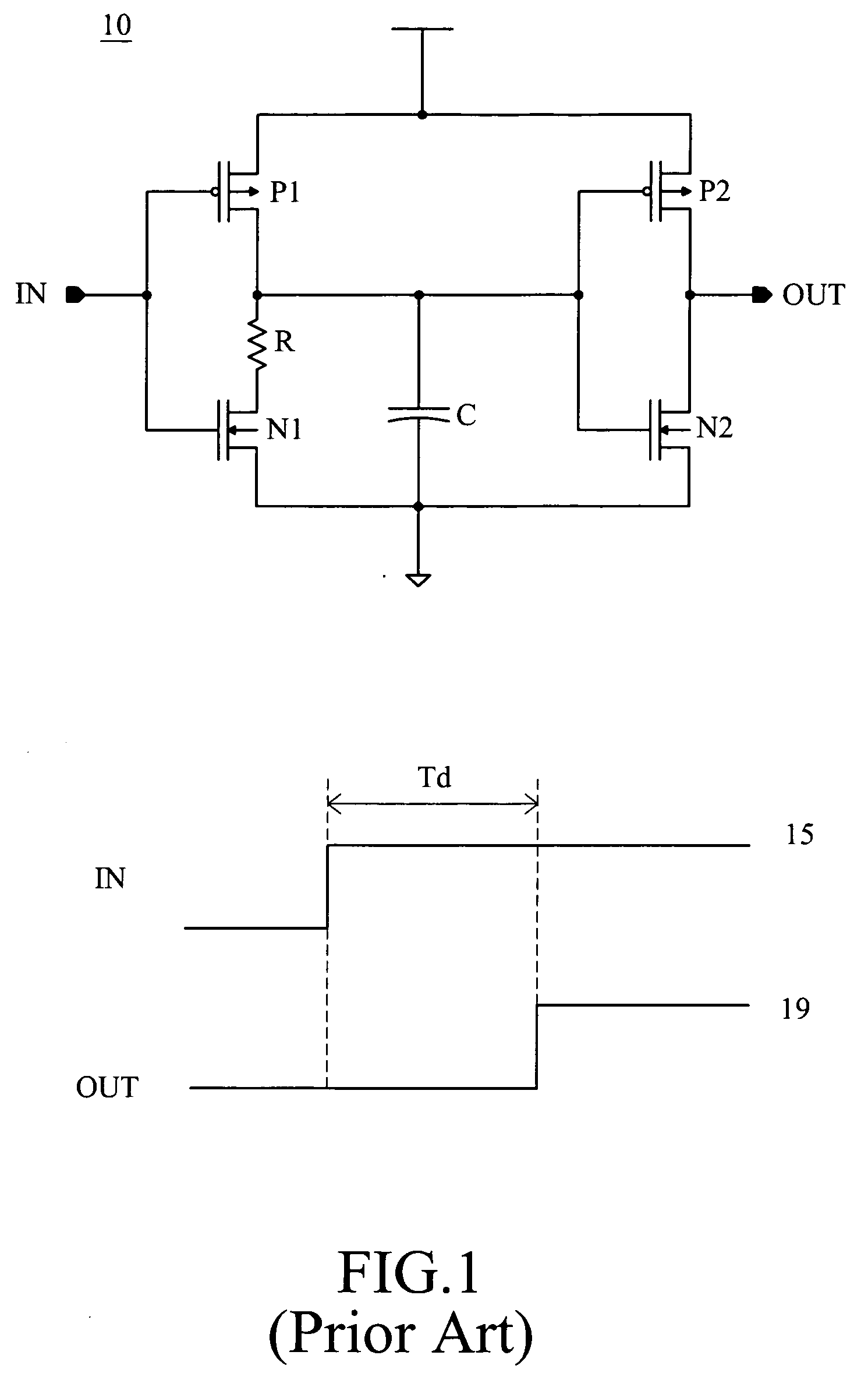
a delay unit and delay time technology, applied in the field of delay units, can solve the problems of difficult to generate accurate delay time td for delay units, and large area delay units b>10/b> that are not beneficial to circuit integration, etc., to achieve accurate control of delay time and reduce the area of delay units

Inactive Publication Date: 2008-07-31
ETRON TECH INC
View PDF9 Cites 8 Cited by
  • Summary
  • Abstract
  • Description
  • Claims
  • Application Information

AI Technical Summary

Benefits of technology

[0006]According to the problems encountered by the above mentioned prior art, a novel delay unit is provided for reduc

Problems solved by technology

But it is very difficult to generate an accurate delay time Td for the delay unit 10 by adjusting the capacitance and resistance of the capacitor C and resister R.
If a large delay

Method used


Image

  • Delay unit
  • Delay unit
  • Delay unit

Examples


Embodiment Construction

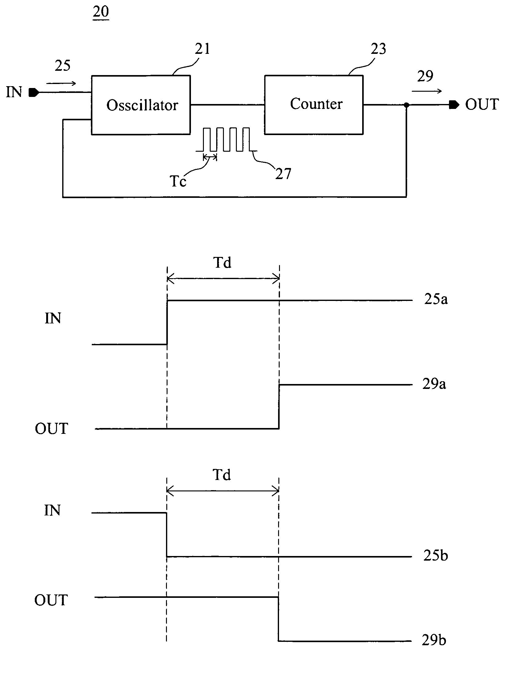
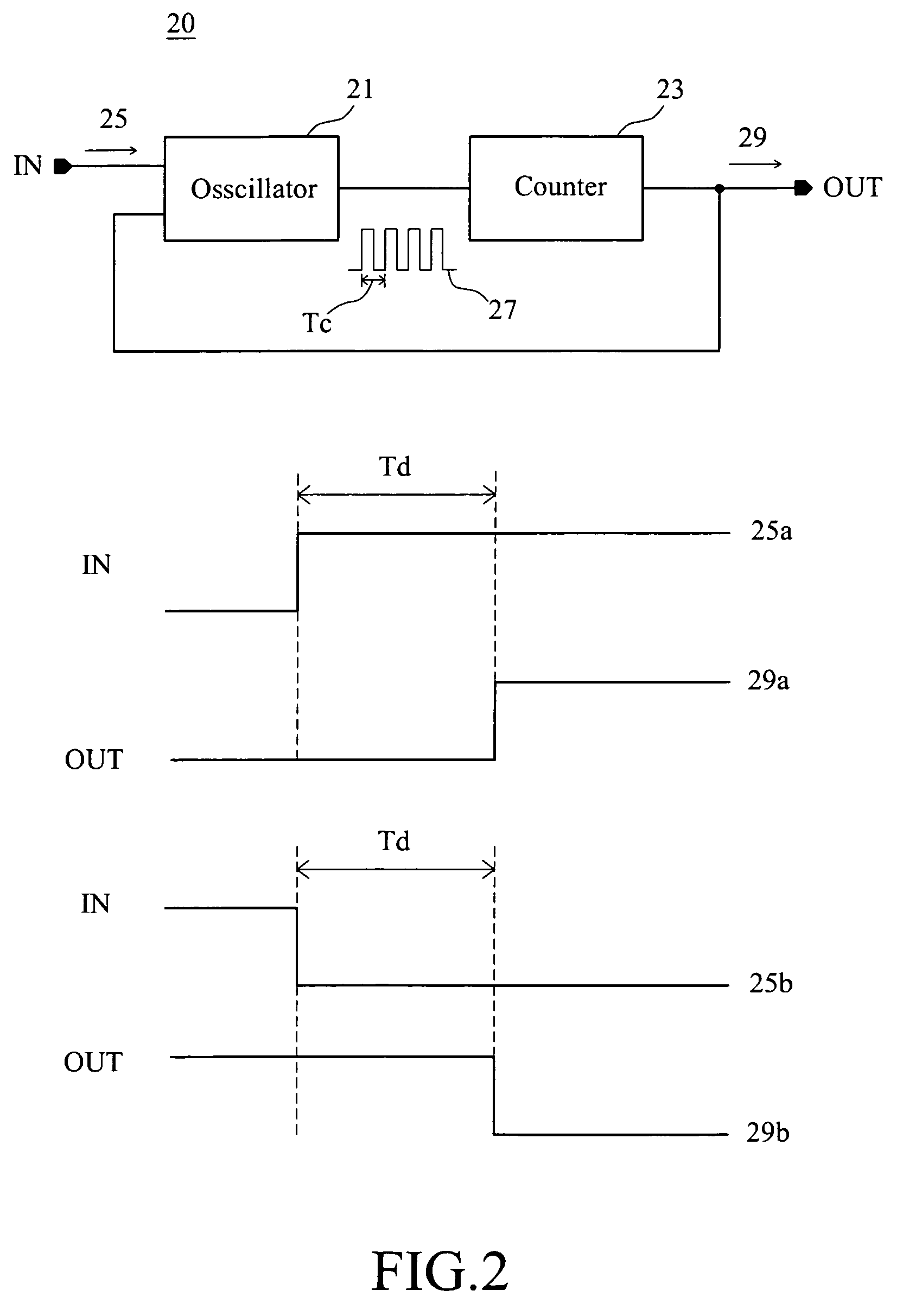
[0022]Referring to FIG. 2 and FIG. 3, there are shown a block diagram and a flow chart of one embodiment of the present invention respectively. The delay unit 20 comprises an oscillator 21 and a counter 23. The oscillator 21 receives an input signal 25 and generates a clock signal 27. The counter 23 is connected to the oscillator 21 for receiving the clock signal 27. It generates a delay signal 29 in response to the clock signal 27 and feeds the delay signal 29 back to the oscillator 21 to stop the oscillator 21.

[0023]The input signal 25 can be a step signal, for example, a step signal 25a from low to high or a step signal 25b from high to low as shown in FIG. 2. When the oscillator 21 receives the input signal 25, as the step 31 shown in FIG. 3, it oscillates and generates a clock signal 27, as the step 32. The clock signal 27 generated by oscillator 21 inputs to the counter 23, as the step 33, and the counter 23 will output the delay signal 29 after a predetermined delay time Td, ...


PUM


Abstract

The present invention is related to a delay unit, and more particularly to a delay unit with respect to delay an input signal. The delay unit comprises a ring oscillator and a counter. The ring oscillator receives an input signal and generates a clock signal. The counter connects to the ring oscillator for receiving the clock signal and generating a delay signal. The delay signal feeds back to the ring oscillator to stop the ring oscillator, and the power consumed in the delay unit can be reduced. The ring oscillator comprises a plurality of inverters and the counter comprises a plurality of flip-flops, and the delay unit can generate an accurately and/or large delay time by changing the number of the inverters and/or the flip-flops.

Description

FIELD OF THE INVENTION[0001]The present invention relates to a delay unit, and more particularly to a delay unit for delaying an input signal.BACKGROUND[0002]FIG. 1 is a circuit diagram of a conventional delay unit. The delay unit 10 comprises a plurality of MOS (P1, P2, N1, N2), a capacitor C and a resistor R. The delay unit 10 receives an input signal 15 and outputs an output signal 19 in response. The output signal 19 is a delay signal with respect to the input signal 15, and a delay time Td is detected between the input signal 15 and the output signal 19.[0003]In this conventional delay unit 10, people change the capacitance of the capacitor C, the resistance of the resistor R or the W / L Ratio of the MOS transistors (P1, P2, N1, N2) to change the value of the delay time Td. For example, we can change the value of the delay time Td according to the requirement of an IC circuit. If the value of the delay time Td generated by delay unit 10 is not too large, for example, in the scal...

Claims


Application Information

Patent Timeline
IPC IPC(8): H03H11/26H03K3/03
CPCH03H11/265H03K2005/00247H03K5/13H03K3/0315
Inventor CHANG, YEN-ANLEE, MING-FOU
Owner ETRON TECH INC
Why Eureka
Try Eureka