
Optical coherence tomography implementation

a coherence tomography and optical coherence technology, applied in the field of optical coherence tomography, can solve the problems of substantial cost associated with an additional dual-balanced photoreceiver and digital acquisition channel, and substantial monetary cost associated with additional detection elements

Active Publication Date: 2008-07-31
VOLCANO CORP
View PDF8 Cites 158 Cited by
  • Summary
  • Abstract
  • Description
  • Claims
  • Application Information

AI Technical Summary

Problems solved by technology

Swept source implementations of PS-FD-OCT have employed two detection channels in a configuration similar to time-domain PS-OCT; however the cost associated with an additional dual-balanced photoreceiver and digital acquisition channel can be substantial.
Additionally, the monetary cost associated with additional detection elements is substantial.

Method used


Image

  • Optical coherence tomography implementation
  • Optical coherence tomography implementation
  • Optical coherence tomography implementation

Examples


Embodiment Construction

[0014]The systems and methods can be understood more readily by reference to the following detailed description of the systems and methods and the Examples included therein and to the Figures and their previous and following description.

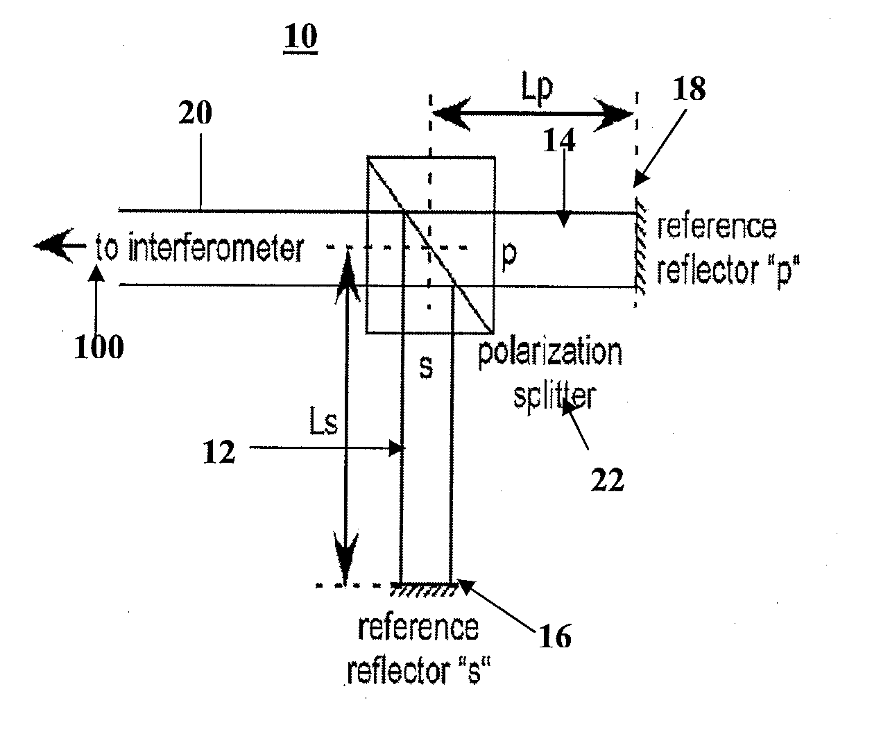
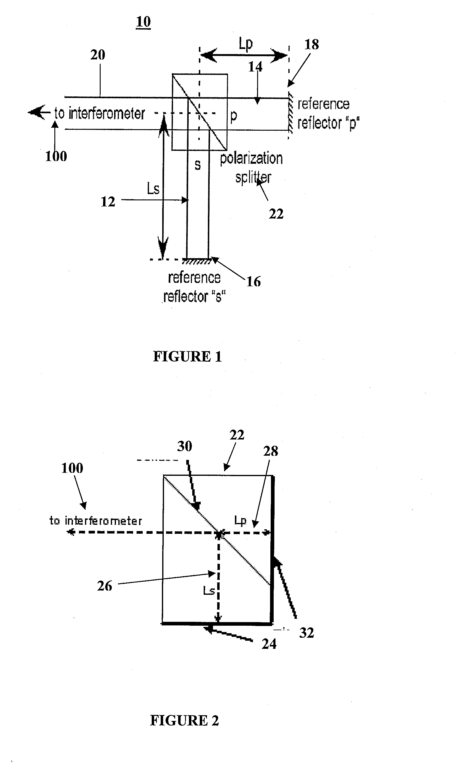
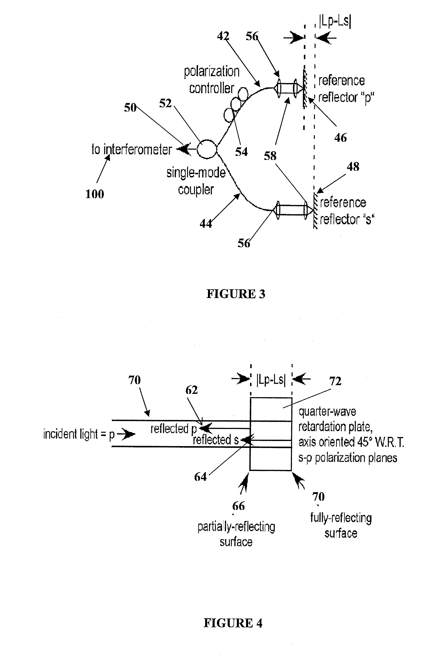
[0015]Generally speaking, the OCT implementation 10 comprises at least two reference paths having a difference in optical path length or time delay, wherein each reference path is associated with a mutually orthogonal polarization state. The OCT implementation generally applies to both spectrometer-based and swept source-based implementations of PS-FD-OCT, and also to both fiber based and bulk-optical and Michelson and Mach-Zender PS-OCT implementations.

[0016]“Implementation” is any instrument or part compatible with the general OCT system in the respective subpart of the OCT system. Generally speaking, the subparts of the OCT system include a light source, a source path, a reference path, and a sample path.

[0017]In one embodiment of the invention, t...


PUM


Abstract

Provided herein are systems, methods, and compositions for optical coherence tomography implementations.

Description

CROSS-REFERENCE TO RELATED APPLICATIONS[0001]The present application claims the benefit of U.S. Provisional Application Ser. No. 60 / 886,226, filed Jan. 23, 2007. The aforementioned application is herein incorporated by reference in its entirety.BACKGROUND OF THE INVENTION[0002]The present invention relates generally to Optical Coherence Tomography (“OCT”), and more specifically to OCT implementations.[0003]In OCT, light from a broad band light source is split by an optical fiber splitter with one fiber directing light to a sample path and the other optical fiber directing light to a reference path mirror. The distal end of the sample path can be interfaced with a scanning device, or the like. The reflected light from the scanning device is recombined with the signal from the reference mirror forming interference fringes, allowing precise depth-resolved imaging or optical measurements to be taken. Conventional OCT thus measures spatially resolved backscattered intensity with a resolu...

Claims


Application Information

Patent Timeline
Patent Type & Authority Applications(United States)
IPC IPC(8): G01B9/02
CPCG01B9/02004G01B9/02028G01B9/02044G01B9/02072G01B9/02069G01B2290/70G01B2290/15G01B9/02091
Inventor KEMP, NATHANIEL J.
Owner VOLCANO CORP
Learn More