Fuel cell system

a fuel cell and system technology, applied in the field of fuel cell systems, can solve the problems of large space required for placing the entire fuel cell stack, the inability to design the layout freely, and the inability to place the fuel cell stack in a small space of a vehicle, so as to reduce the space required

Inactive Publication Date: 2008-07-31
HONDA MOTOR CO LTD
View PDF4 Cites 54 Cited by
  • Summary
  • Abstract
  • Description
  • Claims
  • Application Information

AI Technical Summary

Benefits of technology

[0011]A main object of the present invention is to provide a fuel cell system which makes it possible to suitably prevent protrusion of a cable to the outside of the fuel

Problems solved by technology

Thus, a space required for placing the entire fuel cell stack becomes considerably large.
Therefore, in particular,

Method used


Image

  • Fuel cell system
  • Fuel cell system
  • Fuel cell system

Examples


first embodiment

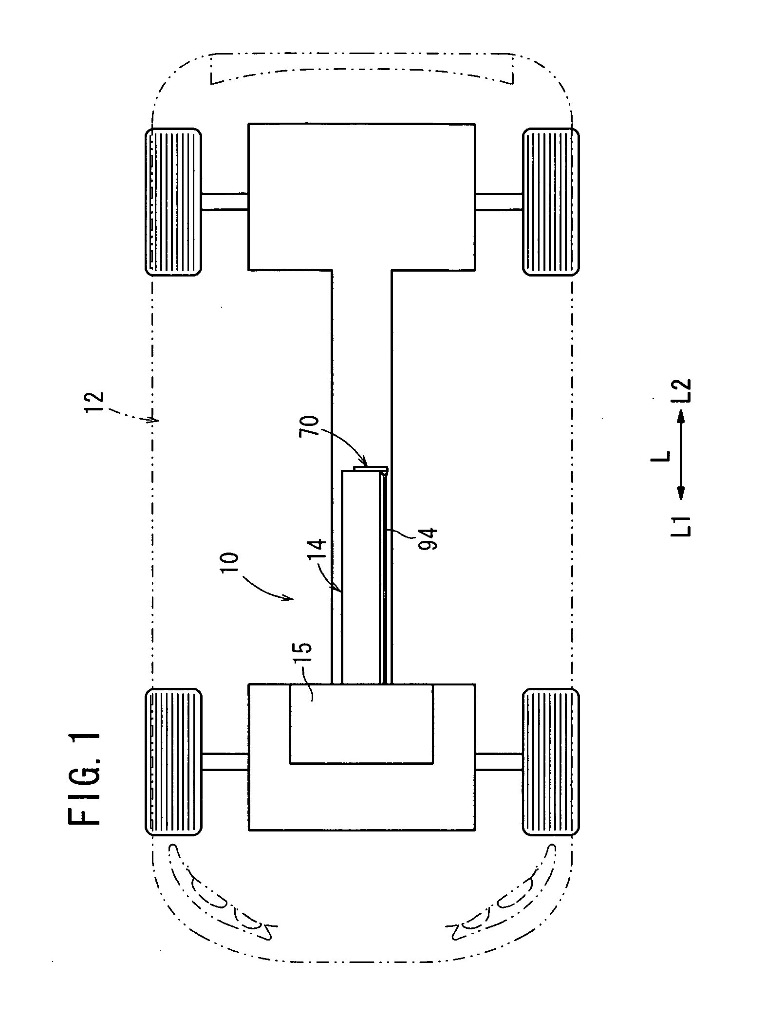
[0026]FIG. 1 is a partial plan view showing a vehicle 12 equipped with a fuel cell system 10 according to the present invention.

[0027]The fuel cell system 10 includes a fuel cell stack 14 provided at a substantially central position in a width direction of the vehicle 12 indicated by an arrow L. A device 15 including a contactor for implementing the ON / OFF control of the supply of electrical energy generated in the fuel cell stack 14 is provided ahead of the fuel cell stack 14 in a travel direction indicated by an arrow L1.

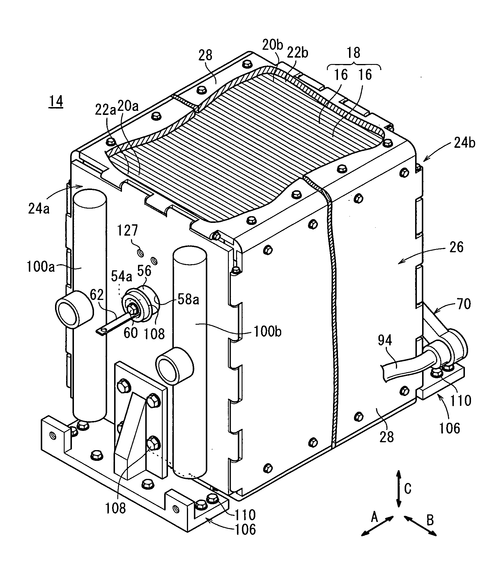
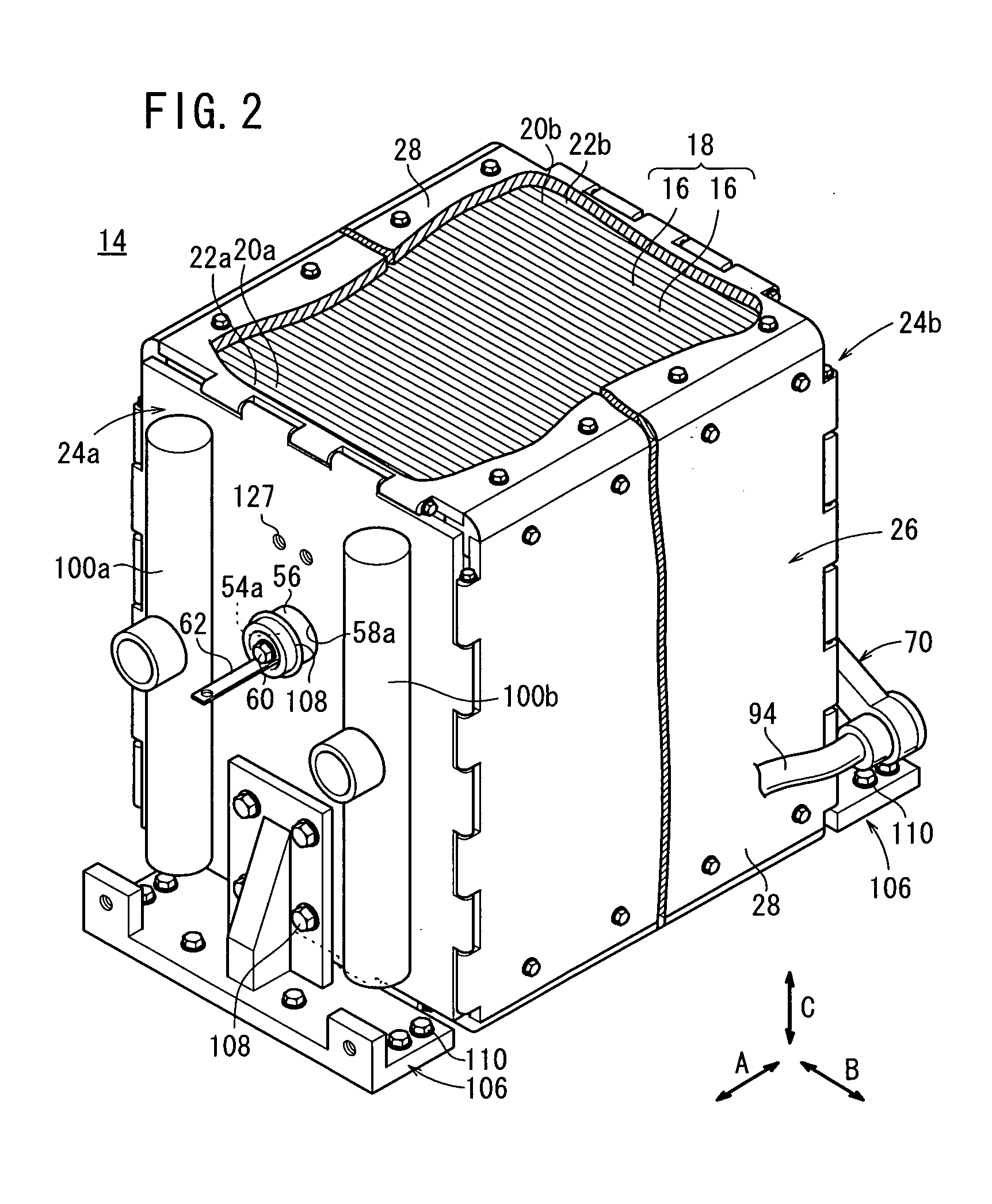
[0028]As shown in FIG. 2, the fuel cell stack 14 includes a stack body 18 formed by stacking a plurality of power generation cells 16 in a horizontal direction indicated by an arrow A. At one end of the stack body 18 in a stacking direction indicated by an arrow A, a terminal plate 20a is provided. An insulating plate 22a is provided outside the terminal plate 20a, and an end plate 24a is provided outside the insulating plate 22a. At the other end of stack body 18...

second embodiment

[0061]In the second embodiment, since the metal layer 124 is formed on the surface of the casing 122 which is made of resin material, and contains the bus bar 68, shielding of electromagnetic waves is performed reliably. This embodiment can be implemented simply by providing the metal layer 124 on the surface of the casing 122. The overall weight of the fuel cell stack 120 is reduced, and the fuel cell stack 120 can be provided in a small space.

third embodiment

[0062]FIG. 7 is a partial cross sectional view showing a fuel cell stack 130 of a fuel cell system according to the present invention.

[0063]The fuel cell stack 130 includes a metal cover (layer of electrically conductive material) 132 around a casing 70 containing the bus bar 68. For example, the metal cover 132 is a thin metal plate.

[0064]In the third embodiment, as in the case of the second embodiment, improvement in shielding of electromagnetic waves is achieved. Further, the overall weight of the fuel cell stack 130 is reduced, and the fuel cell stack 130 can be provided in a small space.


PUM


Abstract

A fuel cell stack includes a stack body formed by stacking a plurality of power generation cells. At opposite ends of the stack body in a stacking direction, end plates are provided. A second power collecting terminal protrudes outwardly from the end plate. One end of a bus bar is electrically connected to the second power collecting terminal such that the bus bar extends along an end plate surface intersecting the second power collecting terminal. A high voltage cable is connected to the other end of the bus bar. The high voltage cable is drawn toward the end plate.

Description

BACKGROUND OF THE INVENTION[0001]1. Field of the Invention[0002]The present invention relates to a fuel cell system including a fuel cell stack comprising a stack body formed by stacking a plurality of power generation cells in a stacking direction, end plates provided at opposite ends of the stack body in the stacking direction, and power collecting terminals protruding outwardly from the end plates. The power generation cell includes an electrolyte electrode assembly and a separator. The electrolyte electrode assembly includes a pair of electrodes and an electrolyte interposed between the electrodes.[0003]2. Description of the Related Art[0004]For example, a polymer electrolyte fuel cell employs an electrolyte membrane (electrolyte). The electrolyte membrane is a polymer ion exchange membrane. A membrane electrode assembly (electrolyte electrode assembly) includes an anode, a cathode, and the electrolyte membrane interposed between the anode and the cathode. The membrane electrode...

Claims


Application Information

Patent Timeline
IPC IPC(8): H01M8/02
CPCH01M8/0247H01M8/2465H01M8/2475Y02E60/50H01M2250/20Y02T90/32H01M2008/1095Y02T90/40H01M8/2483
Inventor MIZUSAKI, KIMIHARUTAKESHITA, TOSHIAKI
Owner HONDA MOTOR CO LTD
Why Eureka
Try Eureka