Hinged Artificial Spinal Disk Drive

a technology of artificial spine and disk drive, which is applied in the field of minimally invasive total disc replacement devices, can solve the problems of unsatisfactory permanent disc fusion, pain lasting for patients, loss of natural body, etc., and achieves the effects of precise placement and positioning, quick recovery time, and easy determination of the success of the operation

Active Publication Date: 2008-07-31
ADL ALI
View PDF27 Cites 50 Cited by
  • Summary
  • Abstract
  • Description
  • Claims
  • Application Information

AI Technical Summary

Benefits of technology

[0002]The invention is a minimally invasive total disc replacement device designed with complimentary easy-to-use insertion and removal instrumentation. The invention offers the surgeon the ability to address Lumbar, thoracic and cervical spinal disc disorders. The invention was designed to allow for either full or partial motion rehabilitation as well as a very quick recovery time. It is secured in place by mechanical means and does not require bone to disc fusion, therefore the success of the operation can be readily determined soon after surgery. It is also self-adjusting and as such, a precise placement and positioning is not required. The design allows for a simple disc removal if needed. Most importantly, the design provides for free movement of the artificial disk within carefully controlled ranges of motion and without extraneous penetration of tissue peripheral to its range of operation.

Problems solved by technology

Although the procedure has advanced greatly and is being performed by microsurgery, allowing relatively quick recovery time, it still has its old problems such as reoccurring herniated or fragmented disc associated with need for repeated surgery, disc thickness reduction and eventually adjacent vertebrae touching each other leading to undesirable permanent disc fusion.
Some of the problems associated with this approach are: (i) loss of natural body motion, (ii) surrounding organs such as muscles may be permanently damaged and may cause lasting pain for the patient and (iii) very long recovery time.
This solution still suffers from drawbacks similar to regular fusion.
Some of the problems with this approach are:
In the case of a successful operation, the fused disc cannot be easily removed if needed.
Operation success rate is only about 80%, which is not an acceptable rate for medical implants.
Extensive surgeon training is required, which is a considerable drawback for the medical society.
In addition, the position of the disk is only limited by the protrusions from the annulus, thus introducing a design trade-off between the danger of the disk falling out of place against the likelihood that the protrusions will be too long thus impacting the neighboring tissue.
This design shows that the link member, when moving back and forth with a piston action, extends out from the plate into the surrounding tissue, causing damage and possibly pain.
With this approach, the amount of angulation is difficult to control: the geometry requires both tiny machining tolerances to have a properly limited motion while at the same time the backing plate has to be thick enough that the angular stress of the link does not twist it.
This approach increases the angular range of motion but with no means to accurately control it.
This increases the risk that the artificial disk will fall out of place necessitating further surgery.

Method used


Image

  • Hinged Artificial Spinal Disk Drive
  • Hinged Artificial Spinal Disk Drive
  • Hinged Artificial Spinal Disk Drive

Examples


Embodiment Construction

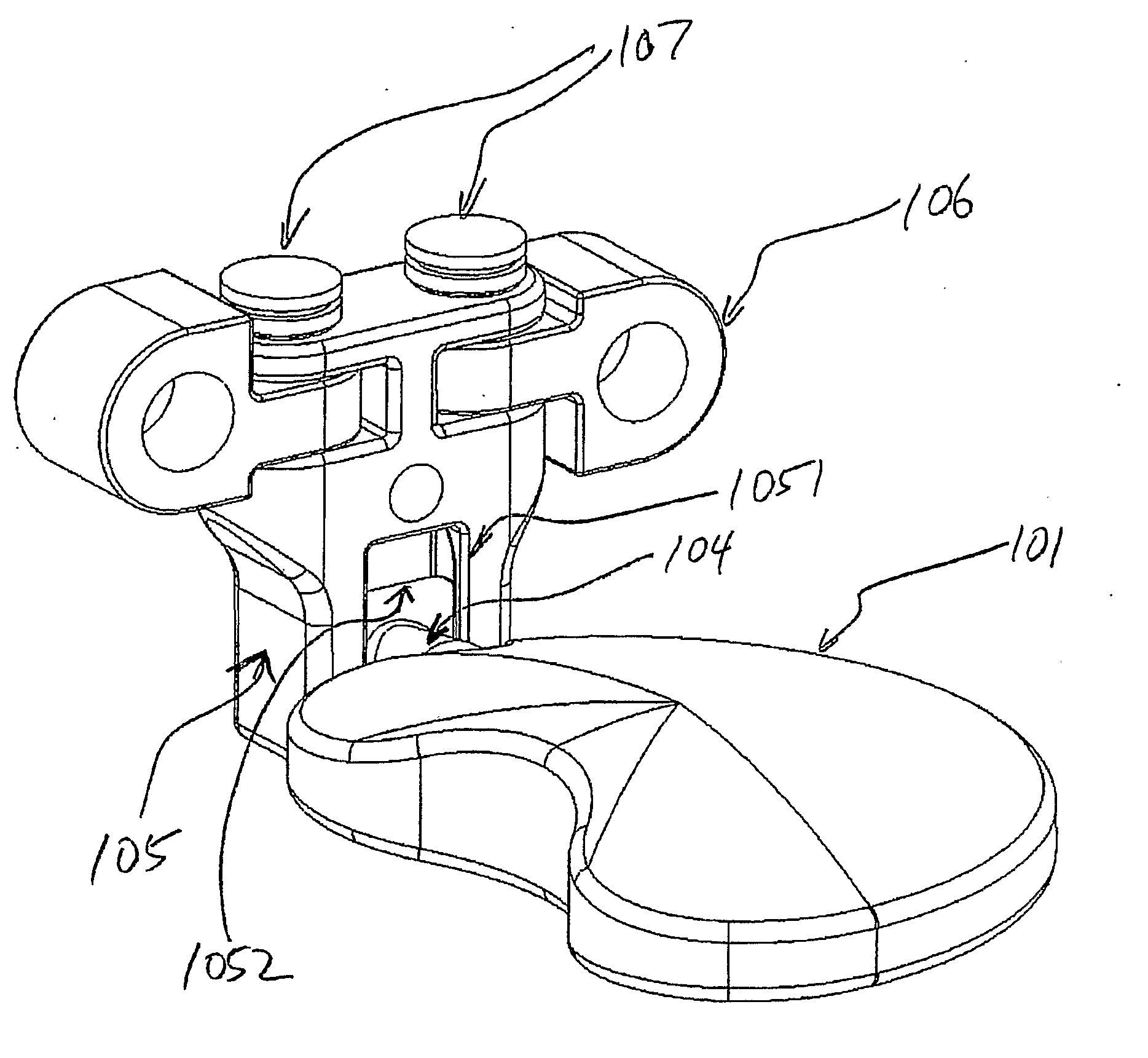
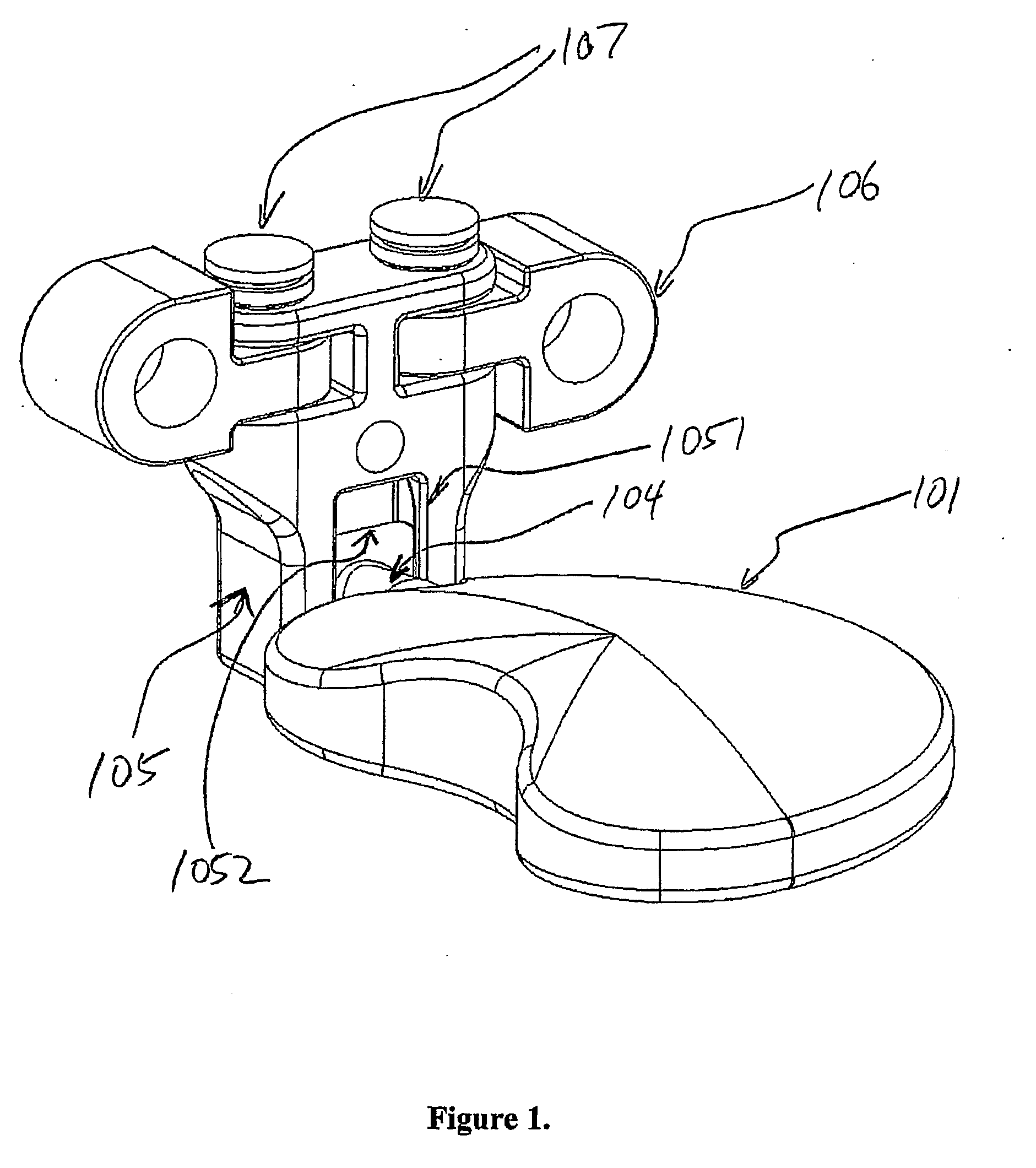
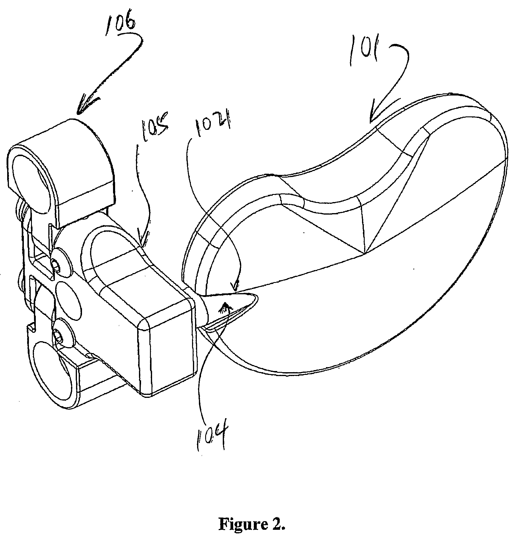
[0021]The device can be divided into three distinct parts: a sliding bracket assembly, a sliding rod and an artificial disk assembly.

Artificial Disk Assembly:

[0022]The artificial disk assembly (101) consists of a central plate as a support mechanism for the upper and lower cushion plates which would be in contact with the vertebrae. The cushion plates are mated to the central plate that lies between them. Alternatively, the artificial disk can be made of one piece of material. The artificial disk is connected to the sliding rod (104) that passes through a hinge (102) and more particularly in the preferred embodiment a collar (102), and the sliding rod is inserted into the sliding bracket (105). In the preferred embodiment, the artificial disk would be solid with upper and lower convex cushion plates to complementarily fit the shape of the opposing faces of the vertebrae. The figures show a horizontal cross section of the disk in the shape of a round or elliptical disc. However the f...


PUM


Abstract

An artificial spinal disk prosthesis comprised of an artificial disk (101), mounting bracket (105) assembly that secures the disk to at least one vertebrae and a sliding rod (104) that connects the two whereby the shape of the components determines the range of motion of the disk, thus allowing desirable motions of the disk consistent with normal body motions and preventing undesirable motions of the artificial disk. In the preferred embodiment, the angular motion of the disk is controlled by a hinge that is on the side of the artificial disk. In the preferred embodiment, the artificial disc is connected to the spine via one vertebra.

Description

REFERENCE TO RELATED APPLICATION[0001]This application claims priority from U.S. Provisional Patent Application Ser. No. 60 / 672,612 filed Apr. 19, 2005, the entire content of which is incorporated herein by reference.BACKGROUND AND SUMMARY OF THE INVENTION[0002]The invention is a minimally invasive total disc replacement device designed with complimentary easy-to-use insertion and removal instrumentation. The invention offers the surgeon the ability to address Lumbar, thoracic and cervical spinal disc disorders. The invention was designed to allow for either full or partial motion rehabilitation as well as a very quick recovery time. It is secured in place by mechanical means and does not require bone to disc fusion, therefore the success of the operation can be readily determined soon after surgery. It is also self-adjusting and as such, a precise placement and positioning is not required. The design allows for a simple disc removal if needed. Most importantly, the design provides ...

Claims


Application Information

Patent Timeline
Patent Type & Authority Applications(United States)
IPC IPC(8): A61F2/44
CPCA61F2/442A61F2310/00179A61F2002/30172A61F2002/30369A61F2002/30372A61F2002/30378A61F2002/3038A61F2002/30471A61F2002/30507A61F2002/30538A61F2002/30578A61F2002/30601A61F2002/30971A61F2220/0025A61F2220/0033A61F2220/0091A61F2230/0015A61F2230/0052A61F2250/0006A61F2310/00017A61F2310/00023A61F2002/30133A61F2002/30331
Inventor ADL, ALI
Owner ADL ALI
Why Eureka
Try Eureka