
Cryopump

a cryopump and fast technology, applied in the direction of positive displacement liquid engines, lighting and heating apparatus, separation processes, etc., to achieve the effect of minimizing the weight of the first stage heat station, reducing the time to warm up during regeneration, and large surface area

Inactive Publication Date: 2008-08-07
SUMITOMO HEAVY IND LTD +1
View PDF30 Cites 6 Cited by
  • Summary
  • Abstract
  • Description
  • Claims
  • Application Information

AI Technical Summary

Benefits of technology

[0021]Reducing the time to cool down is accomplished by minimizing the mass of material to be cooled, most importantly the first stage heat station. Cryodeposit accumulation space is maximized. In combination, both these factors increase the number of cycles after which regeneration becomes necessary.
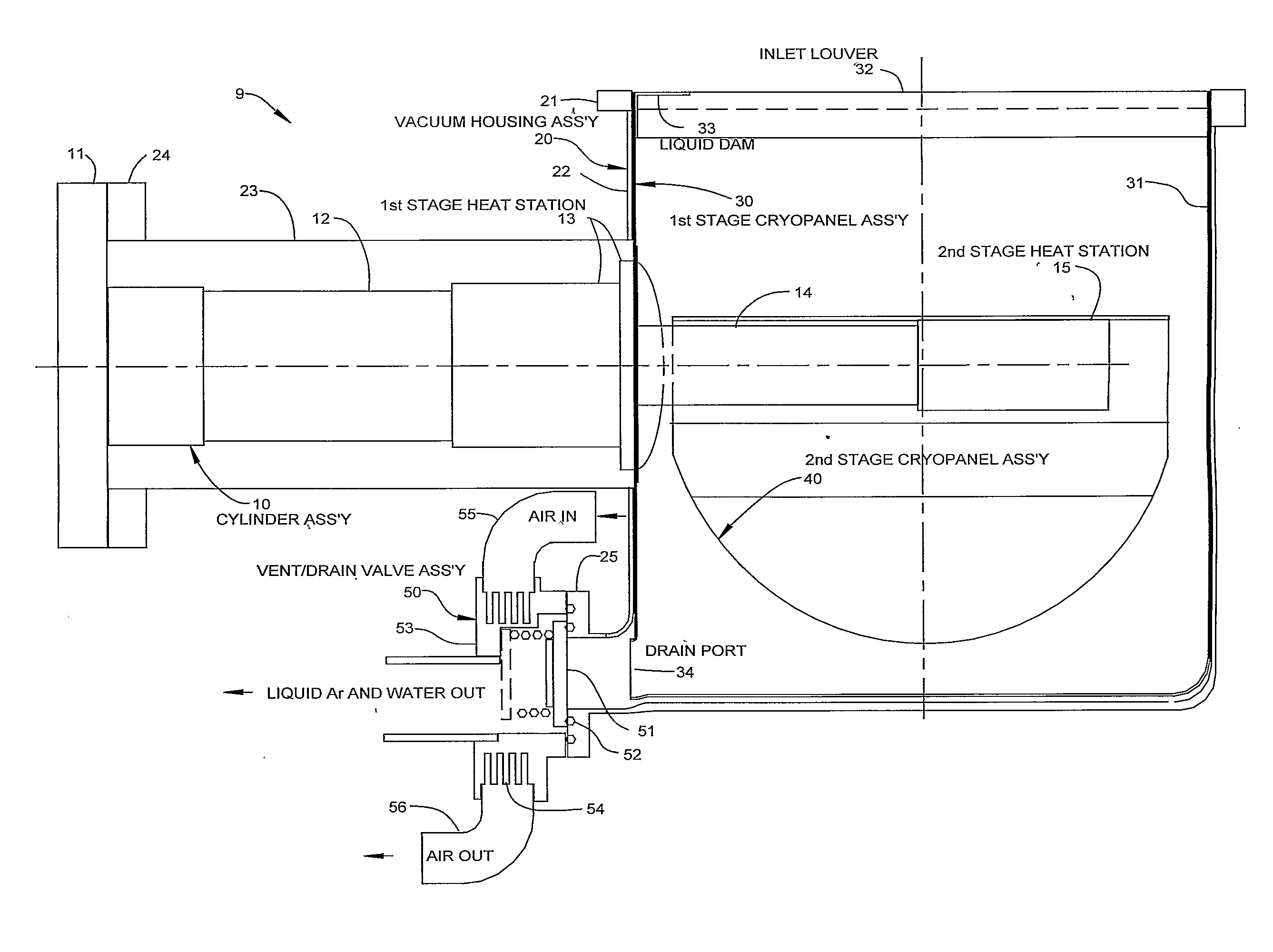
[0023]The invention has three essential features. First, the cold (second stage) cryopanel(s) are in planes that are pitched parallel to the axis of the expander cylinder, (a line can be drawn on a cryopanel surface that is parallel to the axis of the expander cylinder). Second, the cold end of the first stage expansion space is close to the point where the expander cylinder enters the vacuum housing that contains the cryopanels, thus minimizing the weight of the first stage heat station. Third, a drain system results in all of the liquid argon and water flowing out through a vent port for two orientations of the cryopump.
[0024]This arrangement allows a large volume for solid argon to collect fairly uniformly over cryopanels that have a relatively large surface area. More argon can collect and still meet recovery time requirements than is possible with conventional designs. Liquid is drained directly during warm-up. The cryopanel geometry is such that the drain works with the pump in either of two orientations. The second stage heat station does not have to be in the middle of the housing because the folded cryopanel can be attached any place along its length. The panel extends over the second stage cylinder and obviates the need for a separate shield. These features allow more Ar to collect before regeneration is required, time to warm up during regeneration is minimized, and cool down time is minimized.

Problems solved by technology

Third, a drain system results in all of the liquid argon and water flowing out through a vent port for two orientations of the cryopump.

Method used


Image

  • Cryopump
  • Cryopump
  • Cryopump

Examples


Embodiment Construction

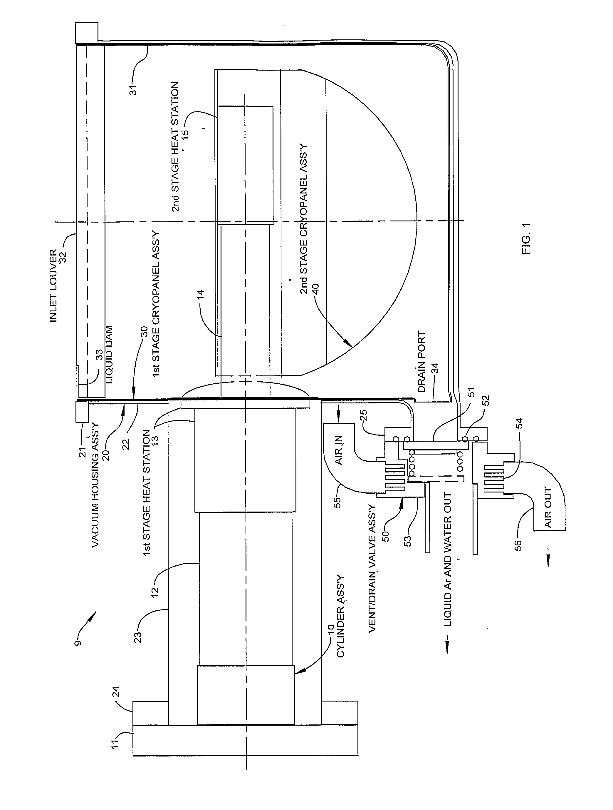
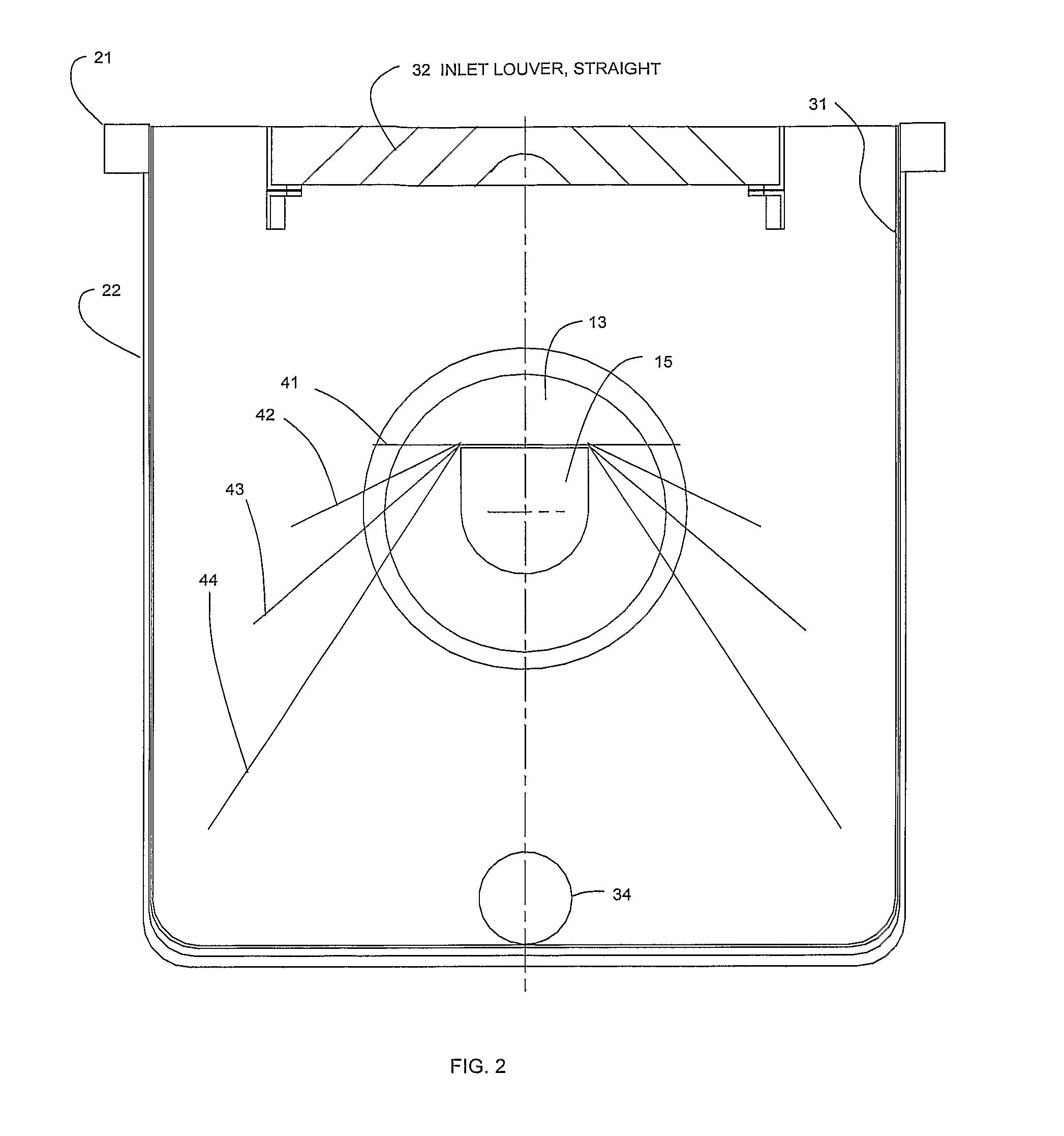
[0028]The side view cross section of cryopump assembly 9 shown in FIG. 1 shows the main components including expander cylinder assembly 10, vacuum housing assembly 20, 1st stage cryopanel assembly 30, 2nd stage cryopanel assembly 40, and vent / drain valve assembly 50. Expander cylinder assembly 10 consists of warm flange 11, 1st stage cylinder 12, 1st stage heat station 13, 2nd stage cylinder 14, and 2nd stage heat station 15. Vacuum housing assembly 20 consists of inlet mounting flange 21, cryopanel housing 22, cylinder housing 23, expander mounting flange 24, and vent / drain port 25. Not shown are mounting ports on cylinder housing 23 that are generally standard for cryopumps to mount a pressure gauge, temperature sensors, purge gas input, and possibly heaters. The 1st stage cryopanel assembly 30 consists of radiation shield 31 (frequently referred to as the warm panel), inlet louver 32, liquid dam 33, and drain port 34. The 2nd stage cryopanel assembly 40 (cold panel) consists of c...


PUM

PropertyMeasurementUnit
Timeaaaaaaaaaa
Lengthaaaaaaaaaa
Temperatureaaaaaaaaaa

Abstract

A cryopump cooled by a GM type refrigerator is disclosed in which the cold (second stage) cryopanel(s) are in planes that are pitched parallel to the axis of the expander cylinder; the cold end of the first stage expansion space is close to the point where the expander cylinder enters the vacuum housing that contains the cryopanels; and a drain system removes all the liquid argon and water flowing out through a vent port for two orientations of the cryopump.

Description

BACKGROUND OF THE INVENTION[0001]The object of the present invention is to provide fast regeneration of a cryopump that is used for sputtering in manufacturing processes such as for the manufacture of semi-conductor wafers. Sputtering typically takes place with a flow of argon at 100 to 200 sccm for a period of about one minute, followed by a cessation of gas flow while the pressure drops to a base pressure of less than 2×10⁻⁷ Torr. Loading of a new wafer occurs in about one minute and the process is repeated.[0002]A throttle plate in front of the cryopump keeps the pressure in the chamber during sputtering at a pressure of about 1×10⁻² Torr while the pressure at the inlet of the cryopump is in the range of 1 to 2×10⁻³ Torr. Since a cryopump removes the gaseous argon by freezing on the second stage (cold) cryopanel, the pump has to be warmed up periodically (regenerated) to melt and remove the argon cryodeposit and then cooled back to normal operating temperatures. Other gases, such...

Claims


Application Information

Patent Timeline
IPC IPC(8): B01D8/00
CPCF25B9/14F04B37/085
Inventor LONGSWORTH, RALPH C.
Owner SUMITOMO HEAVY IND LTD
Learn More