Configurations and Methods for Acid Gas Absorption and Solvent Regeneration

a technology of acid gas absorption and solvent regeneration, which is applied in the direction of liquid degasification, separation processes, dispersed particle separation, etc., can solve the problems of high energy demand for heating and cooling processes in the amine regeneration unit, high cost of ion exchange resin, and need for regenerated or replaced, so as to reduce the duty of reboiler and condenser.

Inactive Publication Date: 2008-08-07
FLUOR TECH CORP
View PDF18 Cites 50 Cited by
  • Summary
  • Abstract
  • Description
  • Claims
  • Application Information

AI Technical Summary

Benefits of technology

[0011]The present invention is directed to configurations and methods of acid gas absorption and solvent regeneration in which the acid gas is absorbed in an absorber having two sections using an ultra-lean solvent and a lean solvent. So generated rich solvent is then regenerated in a regenerator having two sections in which one portion of the rich solvent is employed as a reflux and in which another portion of the rich solvent provides stripping medium to the regenerator, thereby reducing both reboiler and condenser duties. In preferred configurations, the ultra-lean solvent is formed in a separate non-refluxed regenerator using the lean solvent from the regenerator, or formed in a combined regenerator having two or more sections.

Problems solved by technology

Unfortunately, the energy demand for heating and cooling processes in the amine regeneration unit significantly increases with decreasing residual acid gas content in the lean amine.
While such a process reduces steam consumption in the regenerator reboiler, various new disadvantages arise.
Most significantly, ion exchange resins are relatively expensive and need to be regenerated or replaced, and where regeneration is preferred, regeneration transfers the acid gas only from one place to another.
While such a method advantageously reduces the overhead condenser duty to at least some degree, reboiler duty remains largely unaffected, as the amine regeneration process is more strongly dependent on the stripping steam supplied at the bottom of the regenerator.
While such configurations and methods improve gas treatment in at least some respect, other problems remain.
Most significantly, deep removal of acid gases to meet a stringent treated gas specification (e.g., less than 10 ppmv) is typically not achievable, or uneconomic due to the expense of relatively high energy costs in the operation of the regenerator or regenerators.
In addition to the problems associated with the energy demand of amine regeneration, condensation and foaming of heavy hydrocarbons and aromatics in the absorber often renders gas treatment ineffective, and may even cause column instability and / or flooding.
However, a higher lean amine temperature renders hydrogen sulfide absorption less effective due to less favorable amine-hydrogen sulfide equilibrium conditions, which is particularly problematic in low pressure units where the partial pressure of H2S is much lower and less favorable (e.g., to treat tail gas of a sulfur plant).
While integration often simplifies the amine regeneration operation, integration is frequently not energy efficient as lean amine loadings typically vary among different process units.
Thus, use of a single source of lean amine designed for the more demanding treating requirement results in over-stripping for the less demanding units.
This is particularly problematic when an existing facility is expanded to include more demanding units such as the tail gas treatment unit, which would require upgrading the entire amine regeneration system.
Consequently, and especially where stringent emission specifications are encountered, currently known methods and configurations are often neither adequate, nor energy efficient / economical in operation.
Thus, while numerous compositions and methods for acid gas absorption and solvent regeneration are known in the art, all or almost all of them, suffer from one or more disadvantages.

Method used


Image

  • Configurations and Methods for Acid Gas Absorption and Solvent Regeneration
  • Configurations and Methods for Acid Gas Absorption and Solvent Regeneration
  • Configurations and Methods for Acid Gas Absorption and Solvent Regeneration

Examples


Embodiment Construction

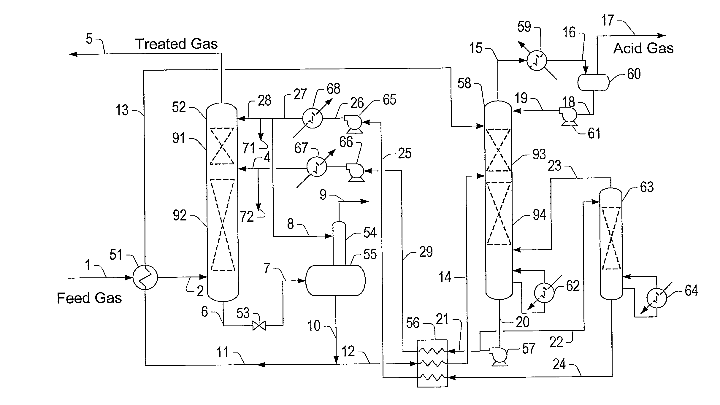
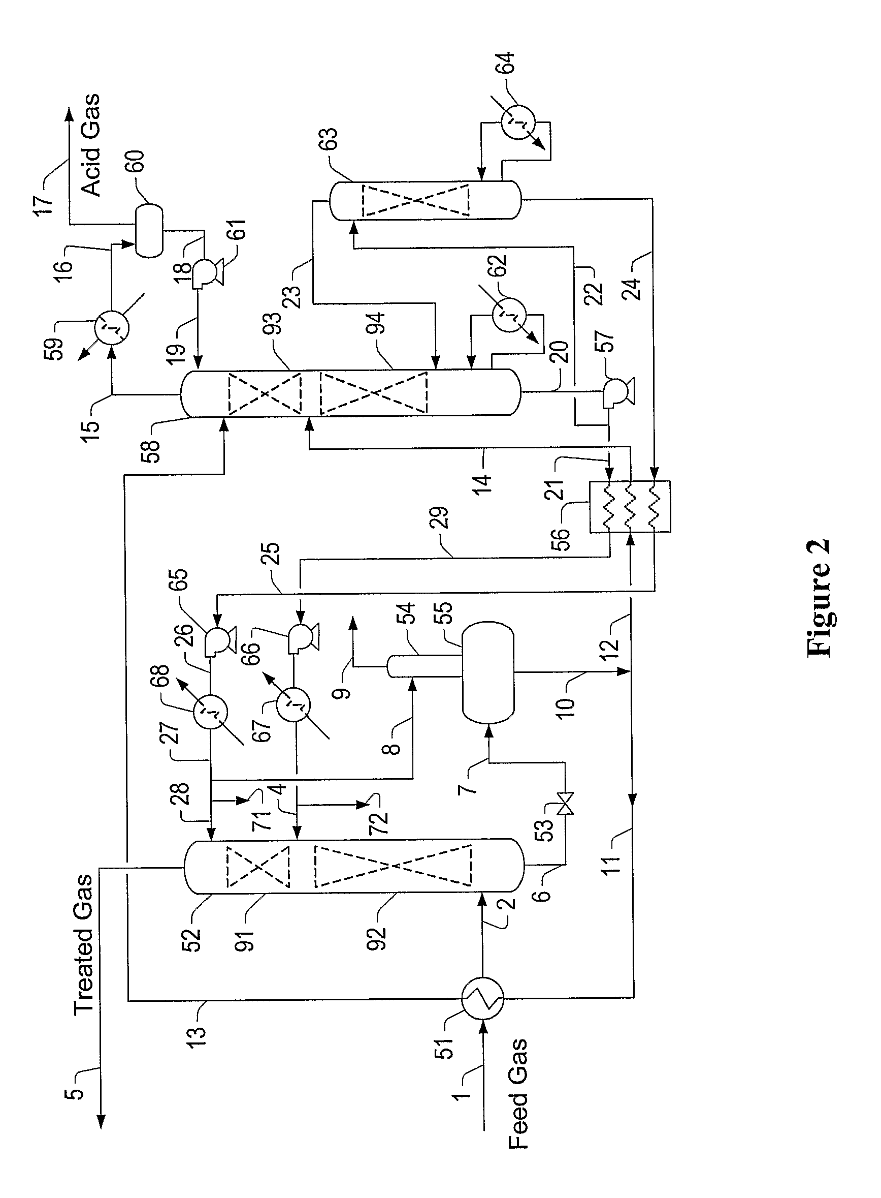
[0027]The inventor has discovered that acid gas absorption and solvent regeneration can be performed in an economically attractive and conceptually simple manner in which the acid gas is adsorbed in a two-stage absorber using a lean (e.g., with 0.01 or higher mole of H2S to mole of amine) and an ultra-lean solvent (e.g., with 0.005 or lower mole of H2S to mole of amine) which are produced in a refluxed and a non-refluxed regenerator, respectively. Most preferably, the refluxed regenerator has two stages and is operated such that cool rich solvent is employed as reflux while heated rich solvent provides at least a portion of the stripping medium. Thus, the reboiler and condenser duties are significantly reduced, even though the stripping can be performed at a higher temperature.

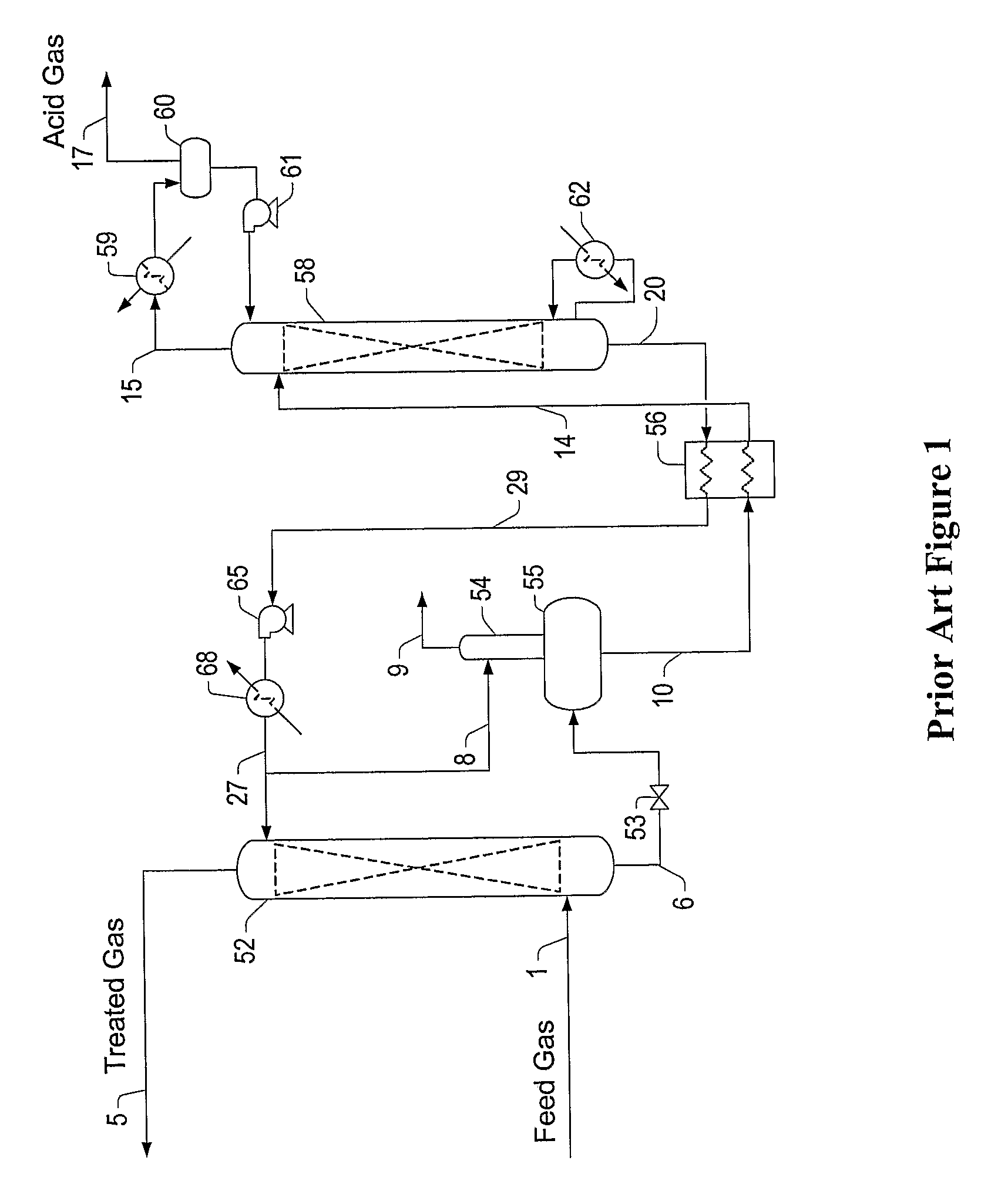
[0028]In contrast, a substantial amount of excess steam in the overhead of currently imown regenerators is required to obtain an adequate degree of stripping in a regenerator. Further, the minimum amount of he...


PUM

PropertyMeasurementUnit
inlet temperaturesaaaaaaaaaa
temperatureaaaaaaaaaa

Abstract

Contemplated configurations and methods include a solvent regenerator (58) that has an upper (93) and a lower stripping section (94). Cooled rich solve is used as reflux while heated rich solvent (11) is used as a source of stripping agent in the upper section (91). A reboiler (62) in the lower section provides further stripping agent, hi especially preferred configurations, a portion of lean solved from the regenerator (58) is further stripped in a separate or integrated regenerator (62) to form an ultra-lean solvent. Both lean and ultra-lean solvents are preferably used in a two-stage absorber (52) to thereby from the rich solvent and an offgas that is very low in acid gas.

Description

[0001]This application claims priority to our copending U.S. provisional patent application with the Ser. No. 60 / 676,131, which was filed Apr. 29, 2005.FIELD OF THE INVENTION[0002]The field of the invention is acid gas removal and solvent regeneration, especially as it relates to absorption of hydrogen sulfide with an amine solvent and regeneration of the rich solvent to produce a lean solvent.BACKGROUND OF THE INVENTION[0003]Acid gas removal from gas streams, and especially removal of hydrogen sulfide and carbon dioxide from gas streams formed in oil / production facilities, refinery process units, and / or synthesis gas production plants is required to avoid release of the acid gas into the environment. Most commonly, the bulk of the sulfur content is converted in a processing unit into elemental sulfur or other commodities (e.g., sulfuric acid, sodium bi-sulfate, etc.), while the tail gas of such processing units is further treated to reduce its sulfur content before venting to the a...

Claims


Application Information

Patent Timeline
Patent Type & Authority Applications(United States)
IPC IPC(8): B01D53/14B01D19/00
CPCB01D53/1468B01D53/1425Y02C20/40
Inventor MAK, JOHN
Owner FLUOR TECH CORP
Why Eureka
Try Eureka