
On-Line Automatic Cleaning Device For A Condenser In A Turbine Generator

a technology of automatic cleaning and turbine generator, which is applied in the direction of flush cleaning, lighting and heating apparatus, and cleaning using liquids, etc., can solve the problems of reducing the getting worse and worse with further operation, and reducing the cost of power generation, so as to increase the heat exchange efficiency of the condenser and reduce the cost of power generation. , the effect of reducing the cost of unit fuel consumption or unit coal consumption

Inactive Publication Date: 2008-08-07
JIANG CONGQUAN
View PDF17 Cites 25 Cited by
  • Summary
  • Abstract
  • Description
  • Claims
  • Application Information

AI Technical Summary

Benefits of technology

[0004]Due to the disadvantage for the currently applied technology, this invention will provide a technical solution for on-line automatic, completely and efficient flushing and cleaning of steam turbine generator set in normal operation status.
[0013]The on-line automatic flushing and cleaning apparatus for steam turbine generator in this invention, with polar coordinate mechanical traveling system to control the high-pressure water jet to reach each Copper tube (or Titanium tube), and perform flushing / cleaning, so as to keep the Copper tube (or Titanium tube) in condenser cleaned efficiently and completely, therefore, the high-pressure water flushing during generator operation can be archived, and increase the heat exchange efficient in condenser, further to reduce the unit fuel consumption or unit coal consumption for steam turbine generator, and reduce the cost for power generating; beside the above, with polar coordinate mechanical traveling system, the apparatus can work in stable condition even with turbulence flow in water pass of condenser, this is the key technology for the on-line automatic flushing / cleaning apparatus in condenser.

Problems solved by technology

Efficiency for condenser will be decreased due to such contamination, and get worse and worse with further operation.

Method used


Image

  • On-Line Automatic Cleaning Device For A Condenser In A Turbine Generator
  • On-Line Automatic Cleaning Device For A Condenser In A Turbine Generator
  • On-Line Automatic Cleaning Device For A Condenser In A Turbine Generator

Examples


Embodiment Construction

[0016]More detailed description for this invention will be present with the attached drawings, while this implement doesn't limit the implement scope of the invention, any similar configuration or modification, shall be within the protection for the invention.

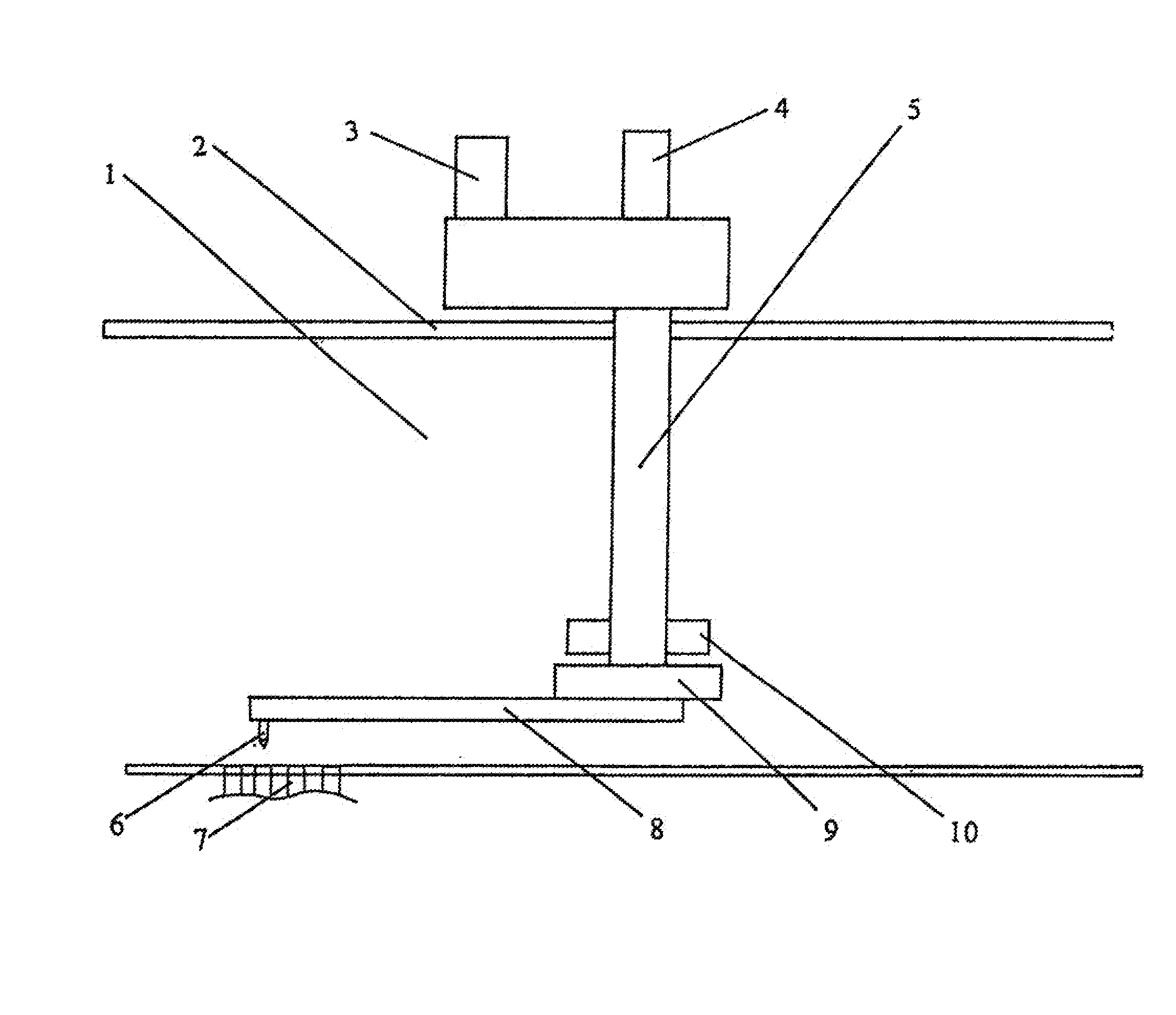
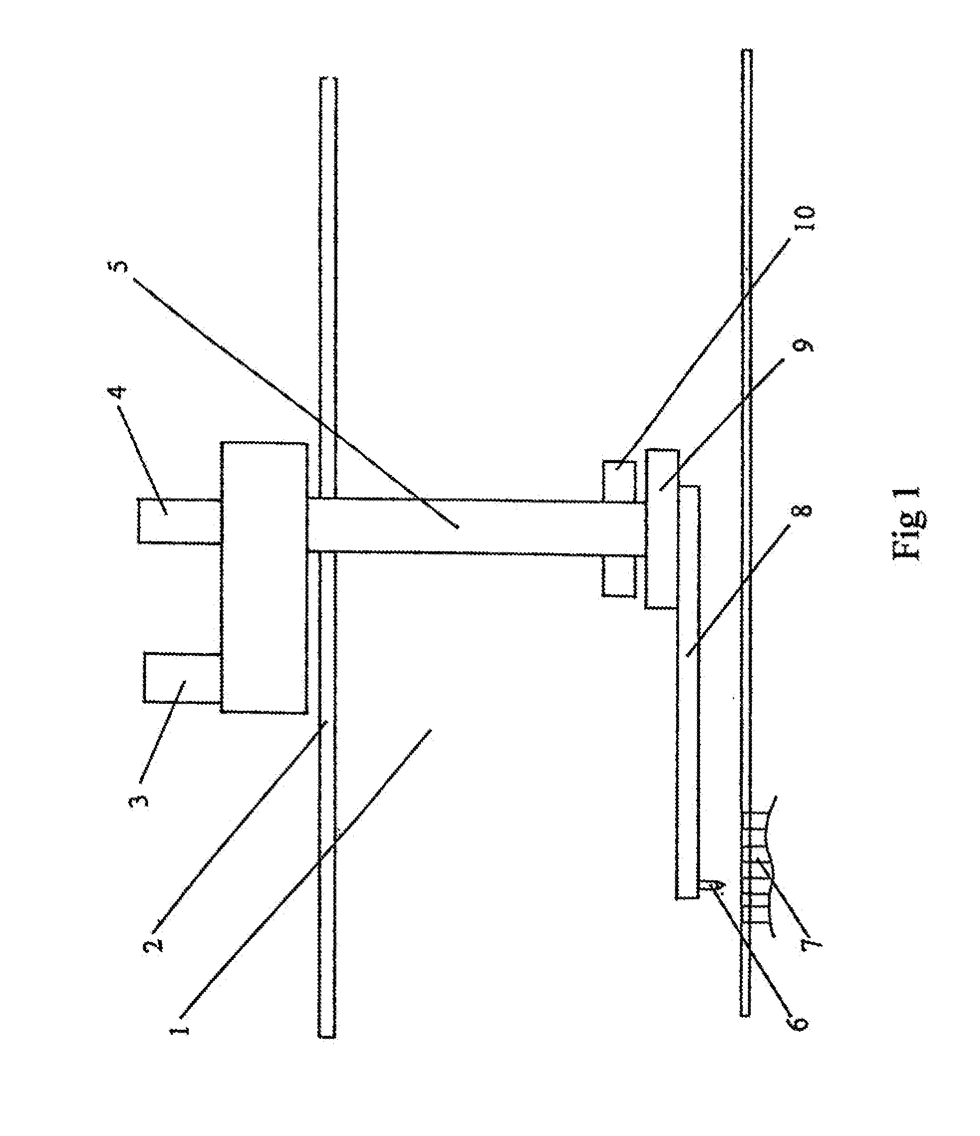
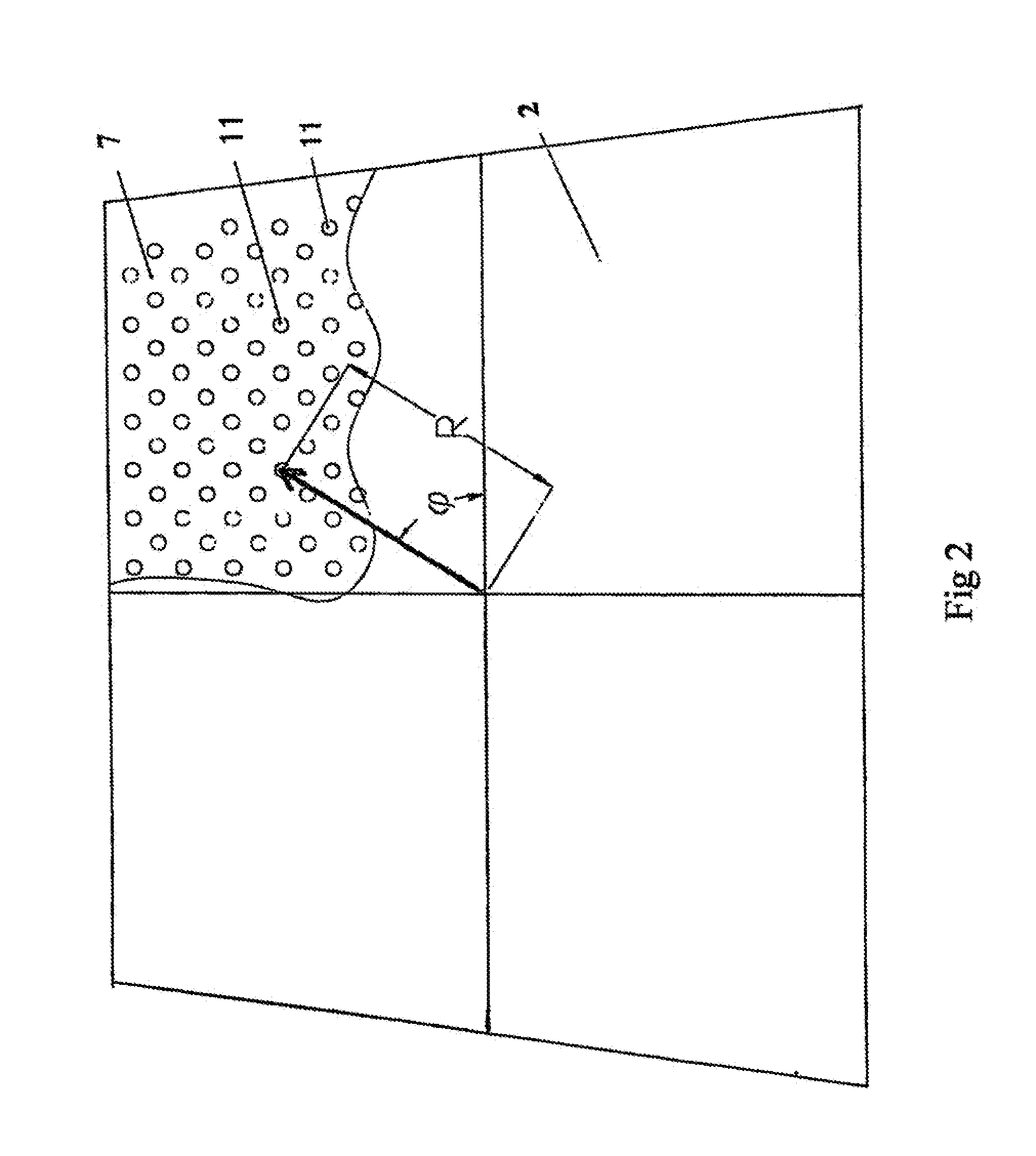
[0017]Referring to FIGS. 1 and 2, in the embodiment, the provided on-line automatic flushing / cleaning apparatus for a steam turbine generator condenser, comprises a high-pressure water jet 6; a polar coordinate traveling mechanical system to control and move a high-pressure water jet 6 across all Copper tubes (or Titanium tube) on a condenser tube plate 7.

[0018]The said polar coordinate traveling mechanical system comprises a computer program polar coordinate control unit (not shown in the Figures), an angle control motor 3, a related transmission structure and a rotating supporting beam 9, a radius moving control motor 4 and a related transmission structure and an extension supporting beam 8. The angle control motor 3 drives t...


PUM


Abstract

A device and method to perform on-line automatic flushing and cleaning for a steam turbine generator condenser, related with technology for flushing and cleaning of equipment during steam turbine generator operation, the apparatus includes: a polar coordinate traveling mechanical system, including one computer program polar coordinate control unit, which will control the servo motors to position the high-pressure water jet on the opening for Copper tube (or Titanium tube); the benefit for the invention is that, the polar coordinate traveling mechanical system move the high-pressure water jet to flush and clean each Copper tube (or Titanium tube) on condenser tube plate, to realize high-pressure water cleaning for each pipe during operation of generator, therefore, the heat exchanging efficient can be increased, further to reduce the consumption of coal for steam turbine generator, and archive the aim to saving coal, and reduction in generating cost.

Description

TECHNICAL FIELD[0001]This invention is related with power generator, especially on-line flushing and cleaning technology and apparatus used in running Steam Turbine Generator condenser, and also heat exchanger.BACKGROUND OF THE INVENTION[0002]Steam condenser, is steam / water heat exchanger, working as the most important auxiliary equipment for steam turbine generator. The heat exchange efficiency for the condenser is directly related with the efficiency of turbine generator, indicated by unit consumption for power generating process, or unit coal consumption for power generating process. The most significant impact factor for the condenser efficiency is the contamination inside the condenser. Usually, cooling water for power plant is river water or sea water, and silt and miscellaneous contamination existing in water will accumulate in water pass. Efficiency for condenser will be decreased due to such contamination, and get worse and worse with further operation. Therefore, as major ...

Claims


Application Information

Patent Timeline
Patent Type & Authority Applications(United States)
IPC IPC(8): F28G1/12
CPCF28B1/02F28G15/08F28G1/163F28B11/00Y02P80/15
Inventor JIANG, CONGQUANYE, XINFU
Owner JIANG CONGQUAN
Learn More