Look-ahead radar and horizon sensing for coal cutting drums and horizontal directional drills

a technology of horizon sensing and radar, which is applied in the direction of measuring devices, cutting machines, instruments, etc., can solve the problems of contamination, reducing the potential for roof fall, and easy-to-mine coal reserves nearing exhaustion, and reducing the gas flow permeability near the boundary

Inactive Publication Date: 2008-08-07
STOLAR
View PDF13 Cites 71 Cited by
  • Summary
  • Abstract
  • Description
  • Claims
  • Application Information

AI Technical Summary

Benefits of technology

[0016]An advantage of the present invention is that a radar is provided that nulls out a strong first reflection that occurs as an earth-penetrating radar wave first enters the soils from the air.
[0017]A further advantage of the present invention is a system is provided for detecting underground objects.
[0018]A still further advantage of the present invention is that a method is provided for controlling mining machines by providing information about the depth of coal deposits in front of them and possible dangers deep in or behind a layer of coal.

Problems solved by technology

Elsewhere, the easy-to-mine coal reserves are nearing exhaustion.
The thin layer reduces the potential for a roof fall, especially along the margins of paleochannels.
The contamination also decreases the gas flow permeability near the boundary.
If the detection sensors are located far away from the cutting edges, feedback control systems on automated machines and gimbals fail to provide closed-loop control.
In-mine drilling slows down mining processes because it requires relocating and repositioning a drilling machine.

Method used


Image

  • Look-ahead radar and horizon sensing for coal cutting drums and horizontal directional drills
  • Look-ahead radar and horizon sensing for coal cutting drums and horizontal directional drills
  • Look-ahead radar and horizon sensing for coal cutting drums and horizontal directional drills

Examples


Embodiment Construction

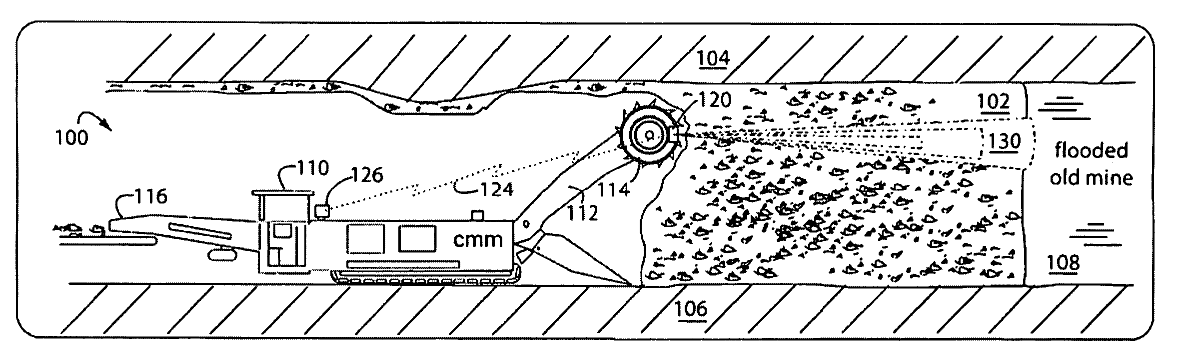
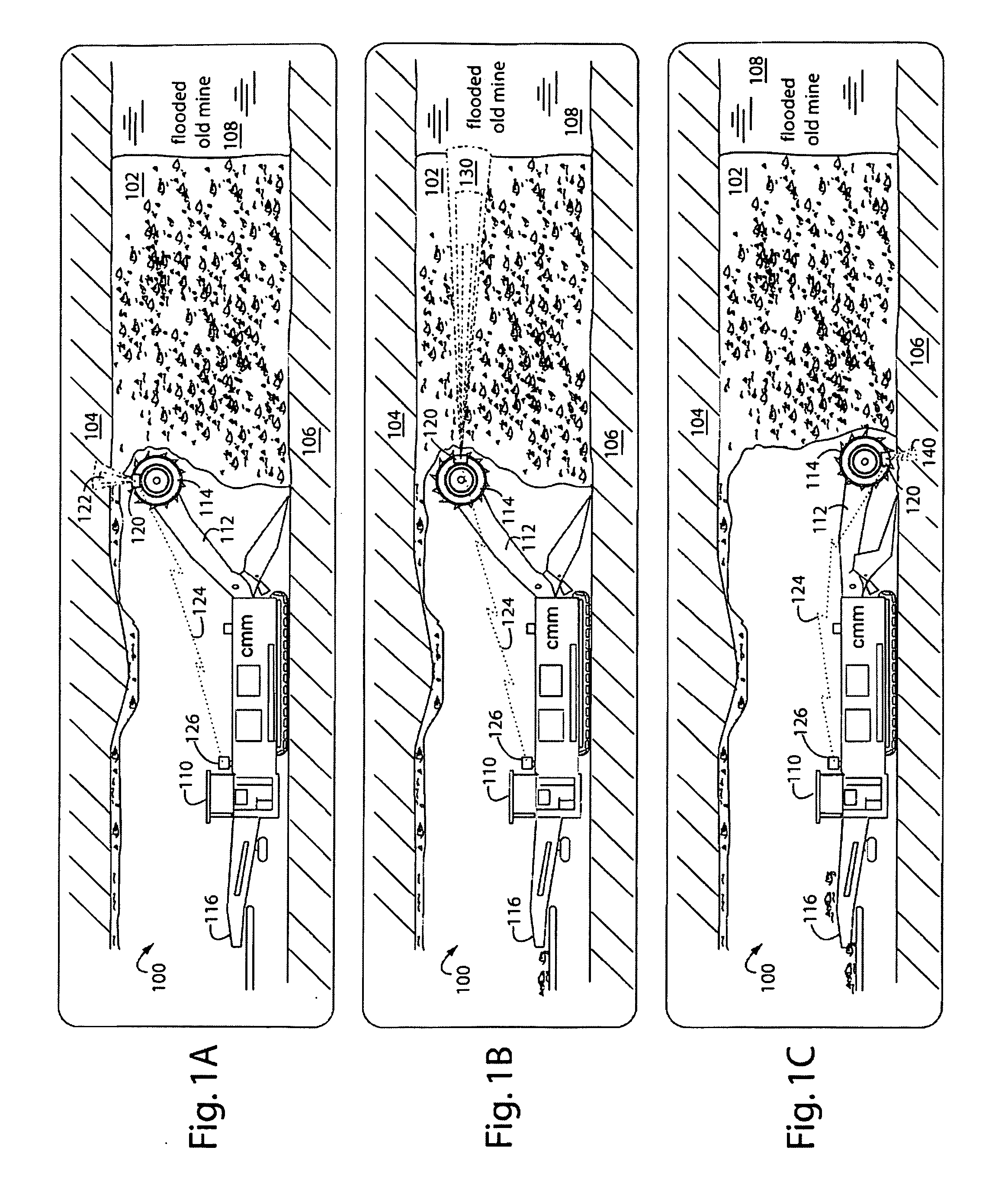
[0034]FIGS. 1A-1C represent a continuous mining machine system embodiment of the present invention, and is referred to herein by the general reference numeral 100. A coalbed 102 has an overburden 104 such as mudstone and / or sandstone, and an underburden 106 such as fireclay. Near the interfaces, the quality of the coal is not so good, e.g., increased levels of sulphur contamination. A typical contaminated coal near the ceiling interface can have a BTU rating of 8,500, sulfur of 5%, ash of 20%, and a density of 1.45. The main coal deposit 102 can be much better, e.g., a BTU rating of 10,680, a sulfur of 0.46%, ash of 7.4%, and a density of 1.3. The real-time horizon sensor enables the machine to leave the contaminated layer of coal in place and improve run-of-mine coal quality.

[0035]In order to exemplify one of the uses of system 100, an old mine 108 adjacent to the works is flooded and presents a grave danger to the miners if a separating barrier pillar wall is punctured. The exact ...


PUM


Abstract

A coal-mining machine uses a ground-penetrating radar based on a software-definable transmitter for launching pairs of widely separated and coherent continuous waves. Each pair is separated by a constant or variable different amount double-sideband suppressed carrier modulation such as 10 MHz, 20 MHz, and 30 MHz. Processing suppresses the larger first interface reflection and emphasizes the smaller second, third, etc. reflections. Processing determines the electrical parameter of the natural medium adjacent to the antenna. Deep reflections at 90-degrees and 270-degrees create maximum reflection and will be illuminated with modulation signal peaks. Quadrature detection, mixing, and down-conversion result in 0-degree and 180-degree reflections effectively dropping out in demodulation.

Description

[0001]This application is a continuation-in-part from both U.S. patent application Ser. No. 11 / 478,757, filed Jun. 29, 2006, and titled EARTH-PENETRATING RADAR WITH INHERENT NEAR-FIELD REJECTION (MLF 654-19), and U.S. patent application Ser. No. 11 / 877,655, filed Oct. 23, 2007, titled DOUBLE-SIDEBAND SUPPRESSED-CARRIER RADAR TO NULL NEAR-FIELD REFLECTIONS FROM A FIRST INTERFACE BETWEEN MEDIA LAYERS (MLF 654-24), and both are incorporated herein by reference.BACKGROUND OF THE INVENTION[0002]1. Field of the Invention[0003]The present invention relates to ground penetration radars, and more particularly sensors that help guide coal mining and directional drilling machinery.[0004]2. Description of Related Art[0005]The United States energy demands for coal and coal-bed methane are increasing faster than 1.8 percent per year. To meet this demand for energy, production will need to be increased by more than 46 percent by the year 2025. Although energy experts believe that coal is abundant,...

Claims


Application Information

Patent Timeline
Patent Type & Authority Applications(United States)
IPC IPC(8): E21C35/08
CPCE21C27/24E21C35/08G01S13/32G01S2007/4082G01S7/4052G01S7/4056G01S13/885G01S7/4082
Inventor BAUSOV, IGORSTOLARCZYK, GERALD L.STOLARCZYK, LARRY G.MAIN, RICHARD B.
Owner STOLAR
Why Eureka
Try Eureka