

Solid Acid Catalyst and Process for Decomposition of Cumene Hydroperoxide
a cumene hydroperoxide and solid acid catalyst technology, applied in the direction of catalyst activation/preparation, physical/chemical process catalysts, bulk chemical production, etc., can solve the problem of reducing the phenol yield
- Summary
- Abstract
- Description
- Claims
- Application Information
AI Technical Summary
Problems solved by technology
Method used
Image

Examples
example 1
[0050]The preparations of zeolite beta layered catalysts of different thicknesses on inner cores of varying diameters for testing in Runs 1 through 12 followed procedures described in U.S. Pat. No. 6,710,003 and more particularly included the following steps.
[0051]A solution of polyvinyl alcohol (PVA) bonding agent (20% by weight), aluminum sol (20% by weight) and de-ionized water (balance) was prepared and mixed for 15 minutes. A pre-weighed amount of zeolite beta powder was blended into this solution and the resulting slurry was stirred for 15 minutes. The amount of zeolite beta used was based on obtaining a final outer layer comprising 70% by weight zeolite and 30% by weight alumina binder, resulting from the incorporation of aluminum sol. A more uniform composition was obtained by ball milling the slurry for two hours, after which the viscosity was adjusted to about 100 centipoise by adding a further amount of de-ionized water.
[0052]A fixed fluidized bed of gamma alumina particl...
example 2
[0053]SAPO-11 layered catalysts were prepared also on gamma alumina spheres of about 1.6 mm diameter as described in the following for the catalyst tested in Runs 15 to 18 as shown in Table 1 below.
[0054]SAPO-11 was synthesized as per procedures described in U.S. Pat. Nos. 4,440,871, 5,126,308 and 5,191,124. A solution of polyvinyl alcohol (PVA) bonding agent (40% by weight), aluminum sol (20% by weight) and de-ionized water (balance) was prepared and mixed for 15 minutes. A pre-weighed amount of SAPO-11 powder was blended into this solution and the resulting slurry was stirred for 15 minutes. The amount of SAPO-11 powder used was based on obtaining a final outer layer comprising 70% by weight zeolite and 30% by weight alumina binder, resulting from the incorporation of aluminum sol. A more uniform composition was obtained by ball milling the slurry for two hours, after which the viscosity was adjusted to about 100 centipoise by adding a further amount of de-ionized water.
[0055]A fi...
example 3
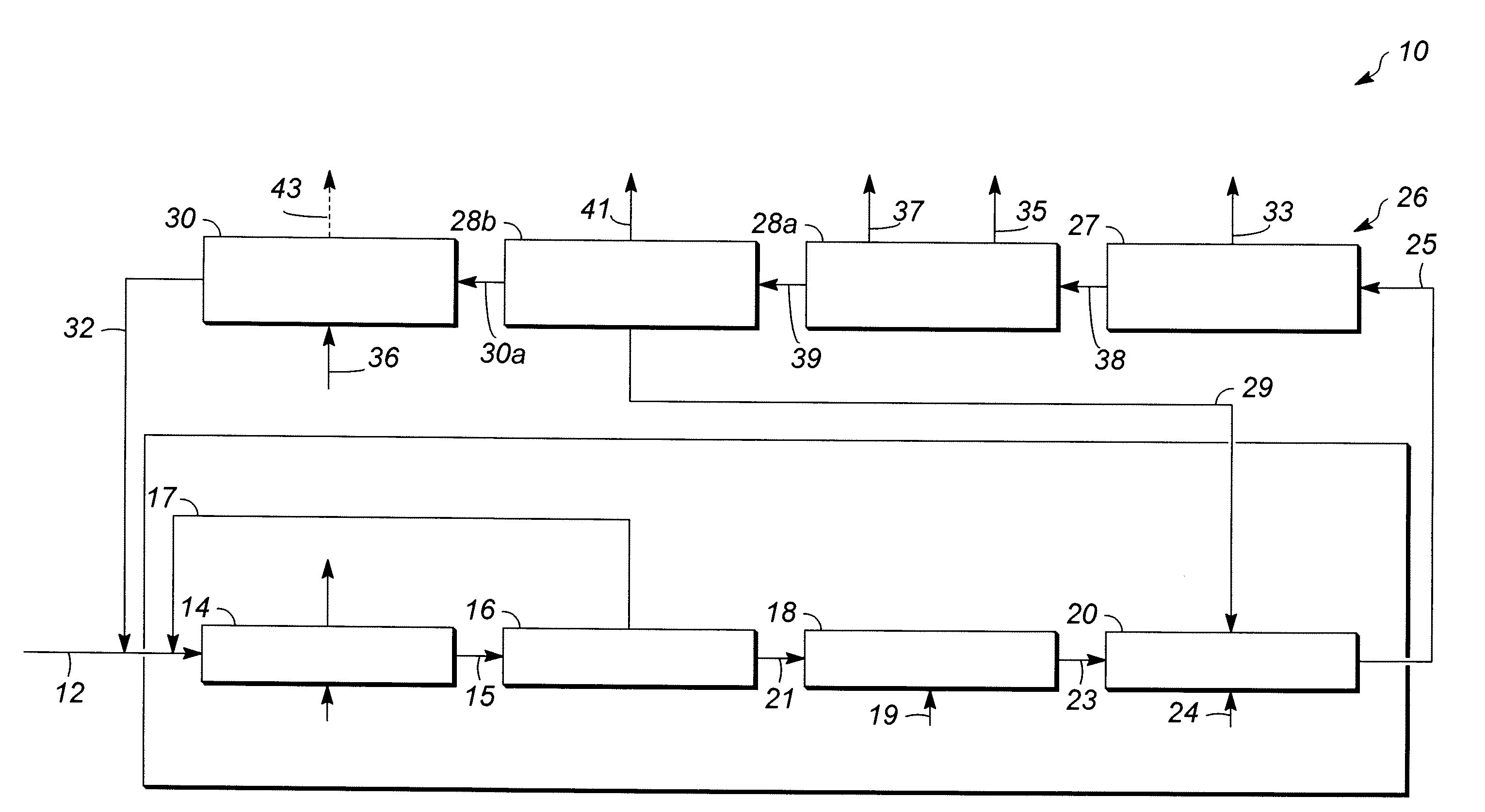
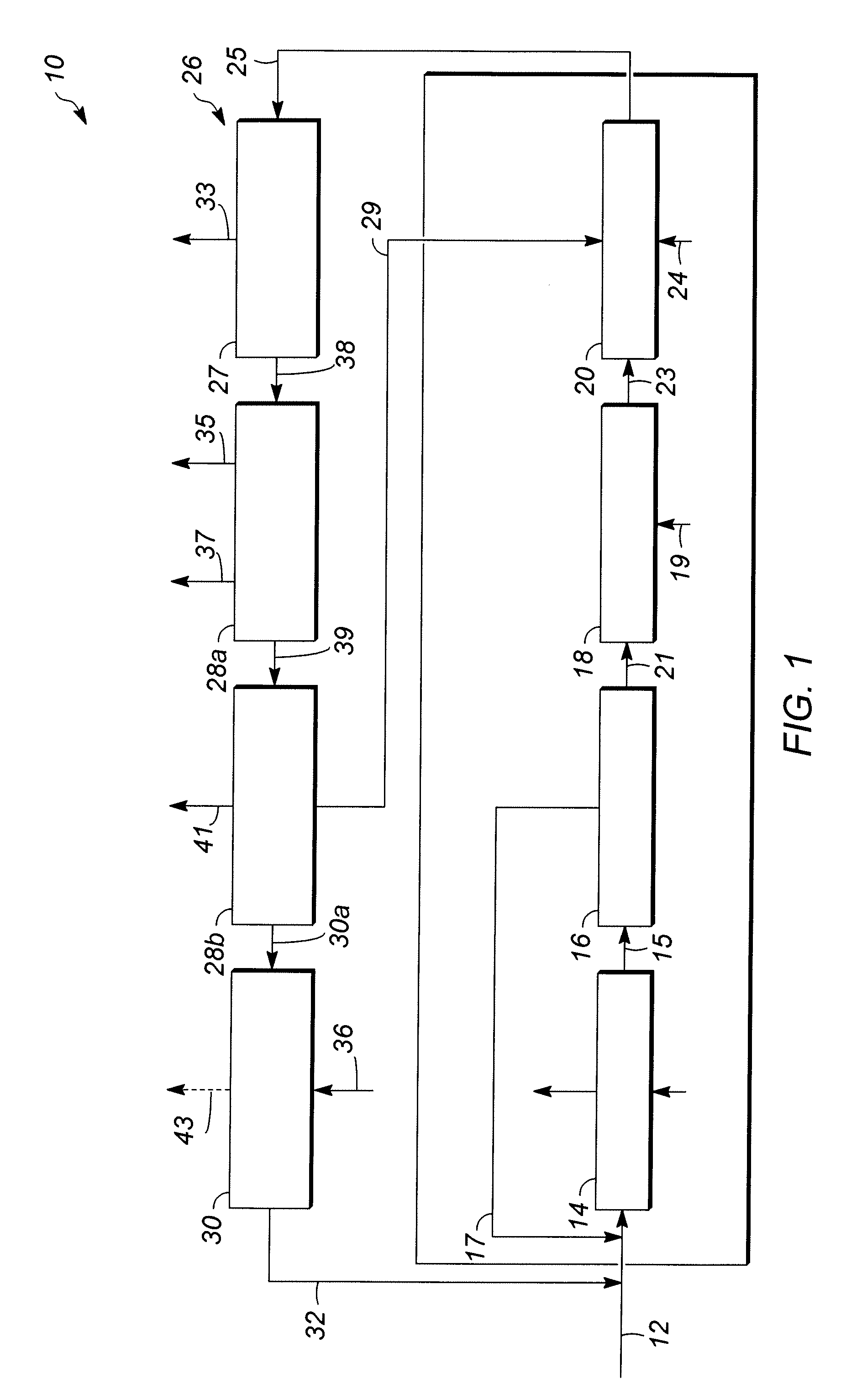
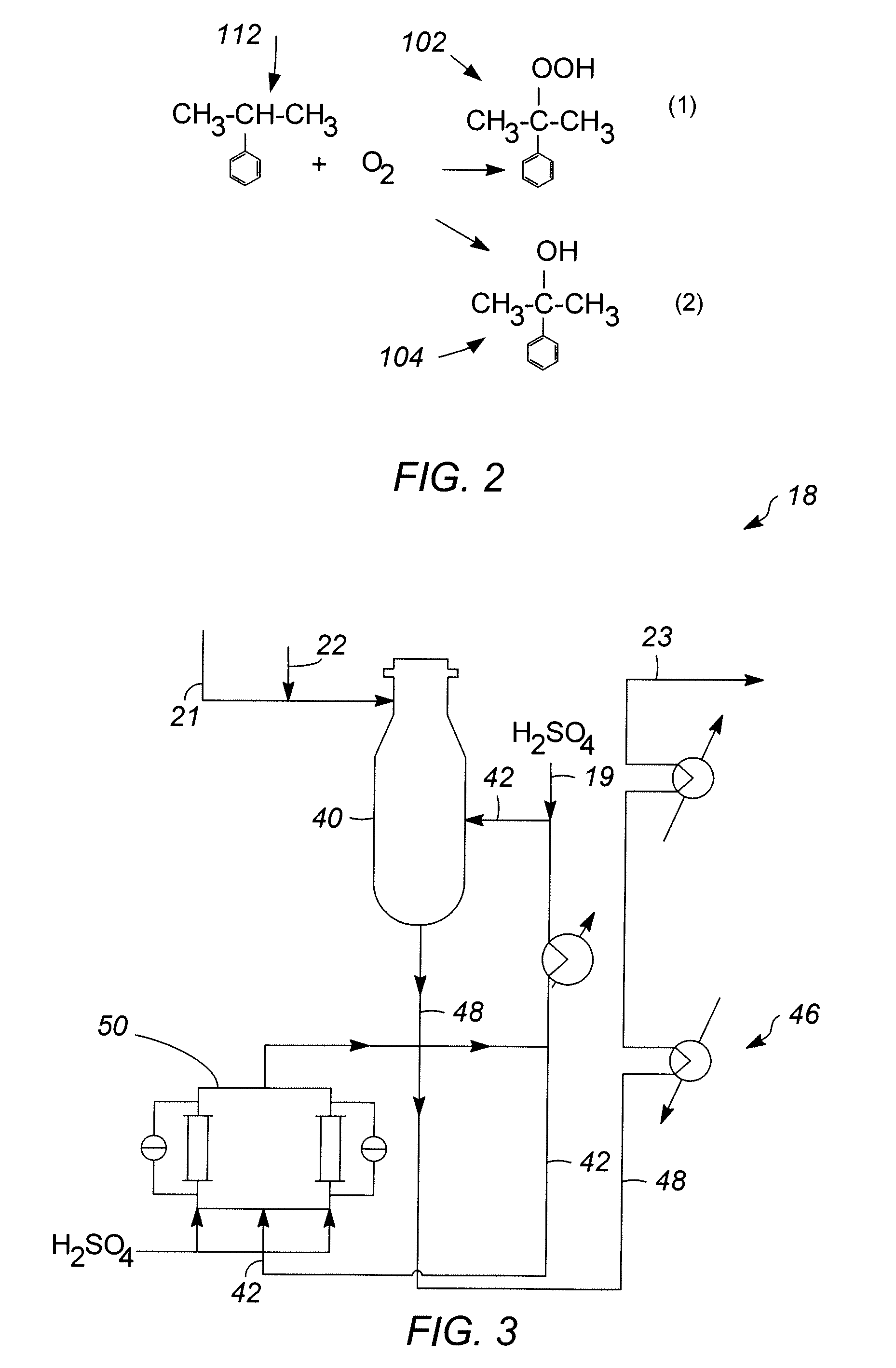
[0057]In Runs 1 to 18, the catalyst samples made in accordance with Examples 1 and 2 and having outer layers of varying thicknesses, set forth in Table 1 below, were screened for activity and selectivity. Runs 1-12 utilized a zeolite beta outer layer having a thickness specified in Table 1. Runs 13-16 and 18 utilized a SAPO-11 outer layer having a thickness specified in Table 1. Run 17 utilized an SM-3 outer layer having the thickness specified Table 1. The catalysts were tested using the following experimental set up. Approximately 4 gms of catalyst were added to 36 cc of a 1:1 molar mixture of acetone / phenol in a 50 cc stirred glass vessel operating as a continuous stirred tank reactor (CSTR) system to simulate the environment of a commercial decomposer reactor. The temperature of the mixture is then raised to about 55° C. to 70° C. and approximately 4 gms of an 85 wt % CHP concentrate solution derived from a commercial phenol unit (see reference numeral 21 of FIG. 1) as a source ...
PUM
| Property | Measurement | Unit |
|---|---|---|
| average particle diameter | aaaaa | aaaaa |
| average diameter | aaaaa | aaaaa |
| average diameter | aaaaa | aaaaa |
Abstract
Description
Claims
Application Information