Variable Compression Ratio Internal Combustion Engine

a compression ratio and internal combustion engine technology, applied in the direction of electrical control, process and machine control, instruments, etc., can solve the problems of long time delay between the pressing of the accelerator pedal and the rising of the supercharging pressure, and it is difficult to achieve satisfactory acceleration performance. achieve the effect of reducing the response delay of the supercharger

Active Publication Date: 2008-08-14
TOYOTA JIDOSHA KK
View PDF4 Cites 20 Cited by
  • Summary
  • Abstract
  • Description
  • Claims
  • Application Information

AI Technical Summary

Benefits of technology

[0006]The present invention has been made in view of the above-described problem of prior arts and has as an object to provide a technology for making it possible to reduce the response delay of a supercharger during acceleration in a variable compression ratio internal combustion engine.

Problems solved by technology

In internal combustion engines in which the above-described technologies are used in combination, if response delay of the supercharger is large, when a request for acceleration is made to the internal combustion engine by, for example, pressing the accelerator pedal, the time lag between pressing of the accelerator pedal and rising of the supercharging pressure becomes long, which sometimes makes it difficult to achieve satisfactory acceleration performance.

Method used


Image

  • Variable Compression Ratio Internal Combustion Engine
  • Variable Compression Ratio Internal Combustion Engine
  • Variable Compression Ratio Internal Combustion Engine

Examples


first embodiment

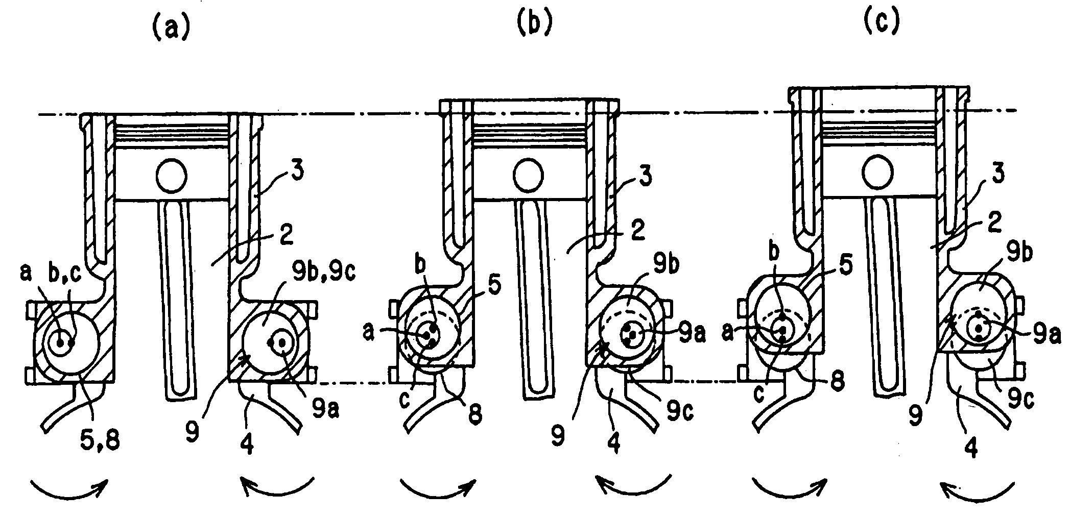
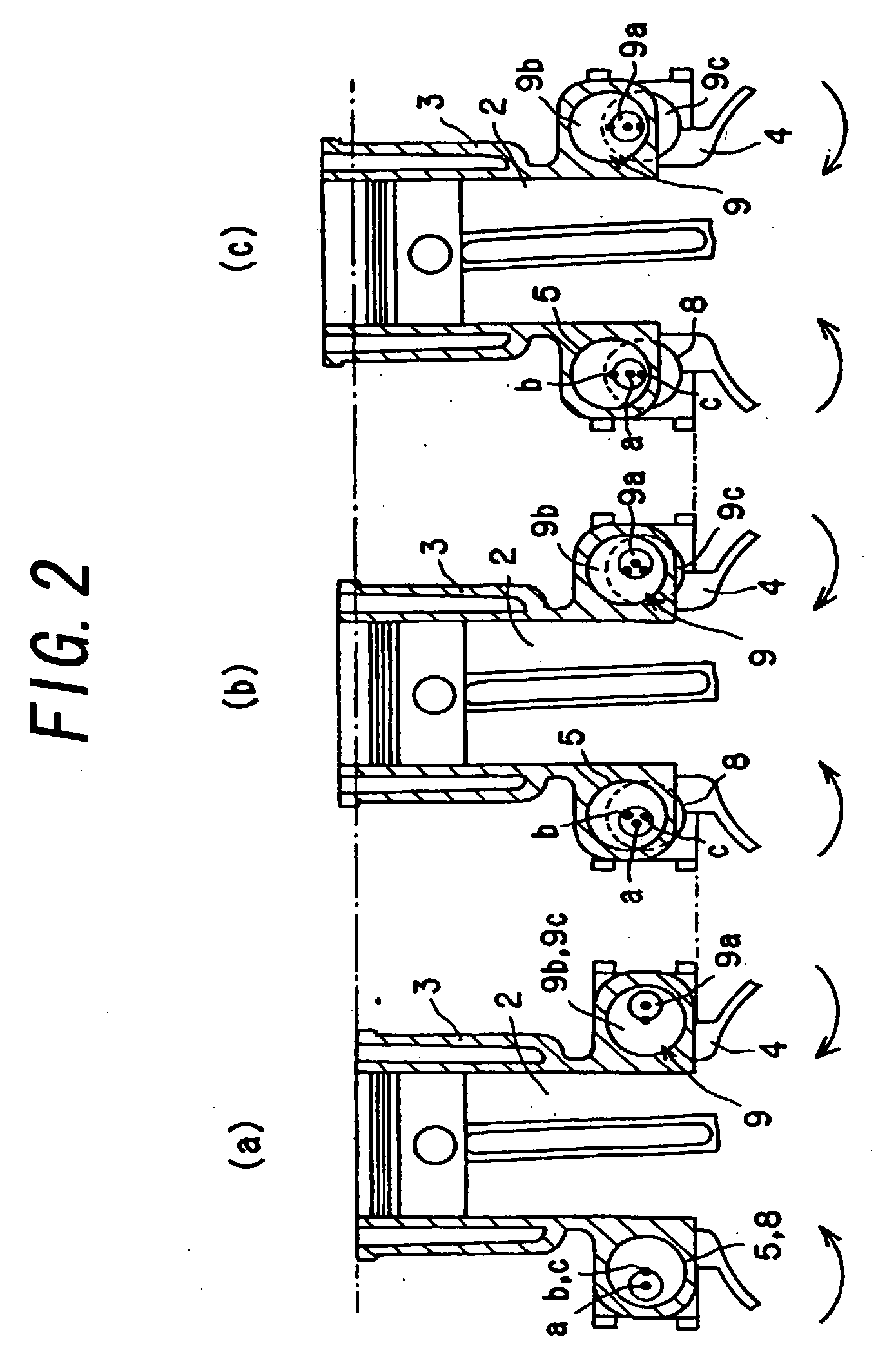
[0042]The internal combustion engine 1 that will be described in the following is a variable compression ratio internal combustion engine, in which the compression ratio is changed by displacing a cylinder block 3 having cylinders 2, along the direction of the center axes of the cylinders 2, relative to a crankcase 4 to which pistons are linked.

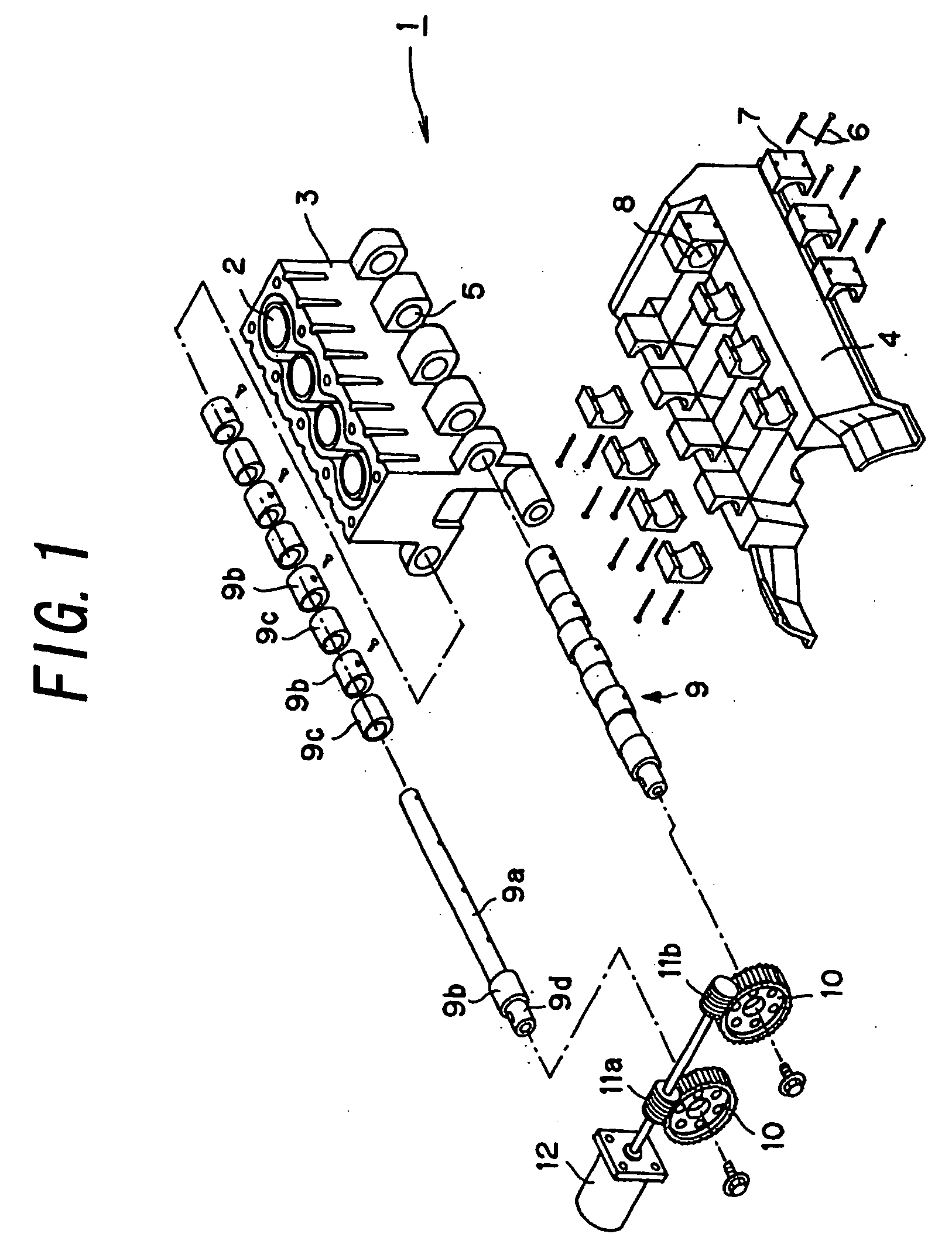
[0043]First, the structure of the variable compression ratio internal combustion engine according to this embodiment will be described with reference to FIG. 1. As shown in FIG. 1, the cylinder block 3 has a plurality of projecting portions formed on both the lower sides thereof. Each projecting portion has a bearing receiving bore 5 formed therein. The bearing receiving bore 5 is cylindrical in shape and extending perpendicularly to the axial direction of the cylinders 2 and parallel to the direction of arrangement of the multiple cylinders 2. The bearing receiving bores 5 on one side are arranged coaxially, and a pair of axes of the bearing...

second embodiment

[0074]In the following, a second embodiment will be described. In the second embodiment, when a request for acceleration is made to the internal combustion engine 1, the optimum compression ratio with which the engine torque becomes maximum is estimated and the compression ratio is changed to the optimum compression ratio while the accelerator pedal is depressed.

[0075]FIG. 7 is a flow chart of a compression ratio changing routine upon acceleration in this embodiment. This routine is a program stored in the ROM of the ECU 35, and executed at predetermined intervals after the internal combustion engine 1 is activated.

[0076]When this routine is executed, firstly in step S101, a determination is made as to whether a request for acceleration is made to the internal combustion engine 1 or not. Specifically, the depression stroke of the accelerator pedal 21 is detected by the accelerator position sensor 22, and a determination is made as to whether the detected value is larger than or equa...


PUM


Abstract

The invention provides a technology that enables to control response delay of the supercharger in a variable compression ratio internal combustion engine under acceleration. When the variable compression ratio internal combustion engine is under acceleration, the compression ratio of the internal combustion engine is set to a compression ratio lower than a basic compression ratio that is so determined in accordance with the running condition of the internal combustion engine to realize a predetermined heat efficiency while suppressing knocking, thereby raising the exhaust gas pressure and shortening the response time of the supercharger.

Description

TECHNICAL FIELD[0001]The present invention relates to a variable compression ratio internal combustion engine in which the compression ratio can be varied.BACKGROUND ARTS[0002]In recent years, technologies for making it possible to vary the compression ratio of an internal combustion engine with a view to improve performance of the internal combustion engine in terms of gas mileage and power etc. have been proposed. In an already proposed technology as such, a cylinder block and a crank case are linked in such a way as to allow their movement relative to each other, and a cam shaft is provided in their link portion to displace the cylinder block and the crankcase toward and away from each other by turning the cam shaft, as disclosed in Japanese Patent Application Laid-Open Nos. 7-26981 and 2003-206771.[0003]In the aforementioned variable compression ratio internal combustion engine, the compression ratio of the internal combustion engine is changed in accordance with the running con...

Claims


Application Information

Patent Timeline
Patent Type & Authority Applications(United States)
IPC IPC(8): F02B75/04F02B33/44F02D15/04F02D23/00
CPCF02B37/00F02B75/041F02D15/04Y02T10/144F02D41/0007F02D41/10F02D35/02Y02T10/12
Inventor AKIHISA, DAISUKEKAMIYAMA, EIICHI
Owner TOYOTA JIDOSHA KK
Why Eureka
Try Eureka