Compounding Thermoplastic Materials In-situ

a thermoplastic material and in-situ technology, applied in the direction of electric/magnetic/electromagnetic heating, rotary stirring mixers, furnaces without endless cores, etc., can solve the problems of clogging the dispensing apparatus, preventing common vacuum handling at the melting and dispensing, and unable to palletize semi-solid materials

Inactive Publication Date: 2008-08-14
LASKO BERNARD
View PDF30 Cites 19 Cited by
  • Summary
  • Abstract
  • Description
  • Claims
  • Application Information

AI Technical Summary

Benefits of technology

[0006]The invention relates to the combining, melting, and mixing of thermoplastic materials only in quantity as continuously required at the application site. This minor quantity in fast process can avoid additives, time at temperature and atmosphere degradation, and application process start-up delays.

Problems solved by technology

Other materials form a char (solids in the melt that have to be filtered) that clogs the dispensing apparatus after extensive heat exposure.
Some semisolid materials cannot be palletized.
Some formulations of palletized materials stick together and therefore preclude common vacuum handling at the melting and dispensing site.

Method used


Image

  • Compounding Thermoplastic Materials In-situ
  • Compounding Thermoplastic Materials In-situ
  • Compounding Thermoplastic Materials In-situ

Examples


Embodiment Construction

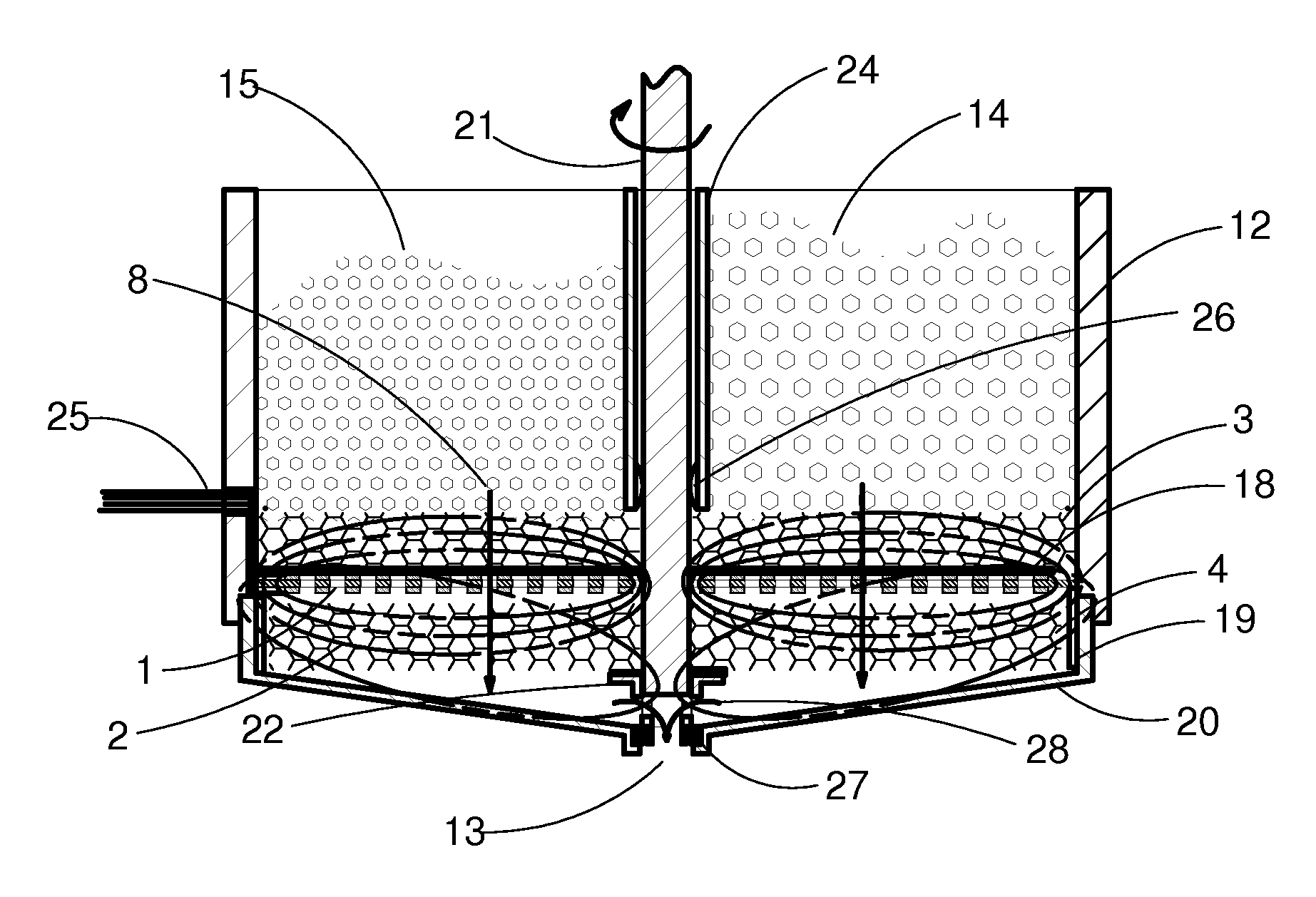
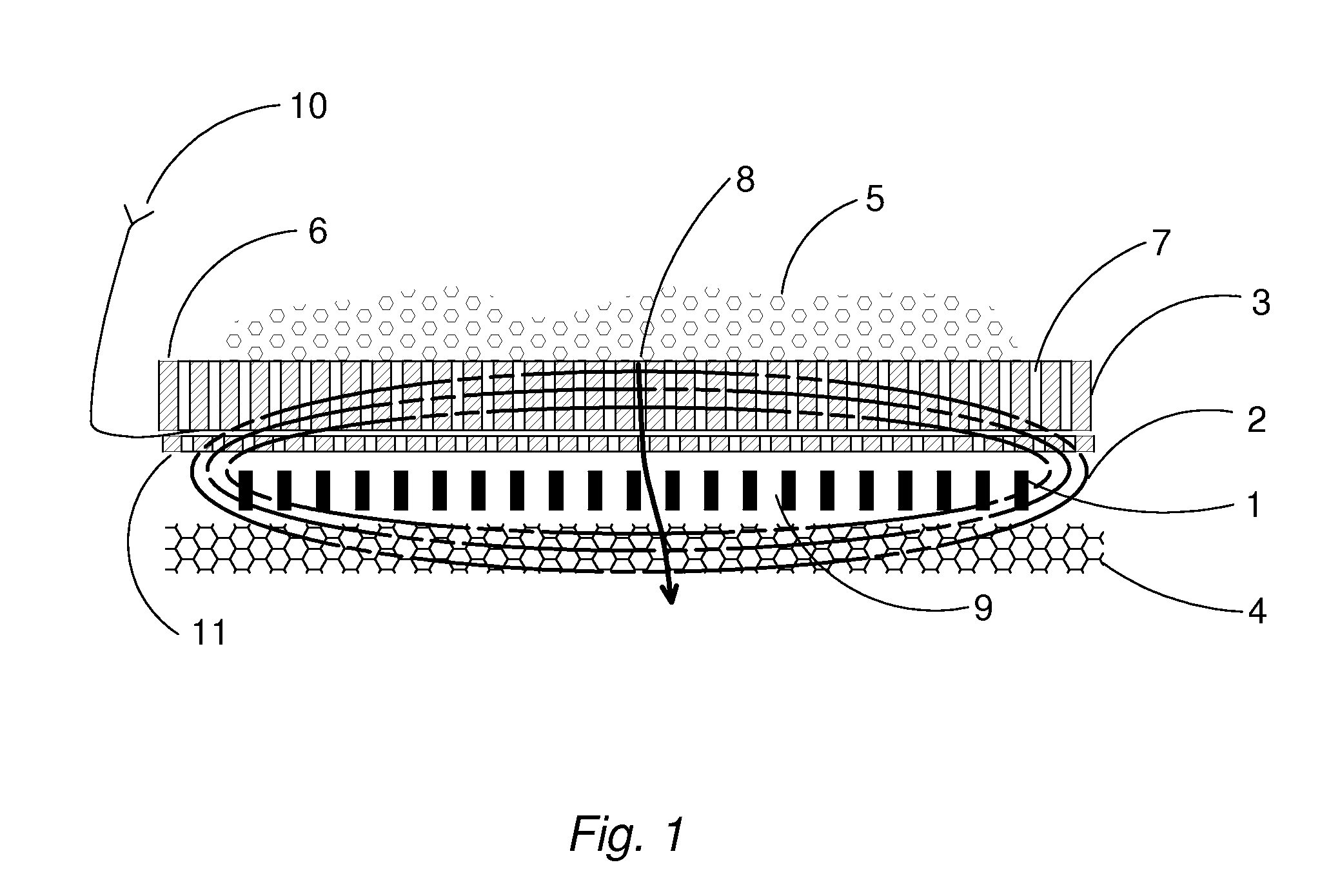
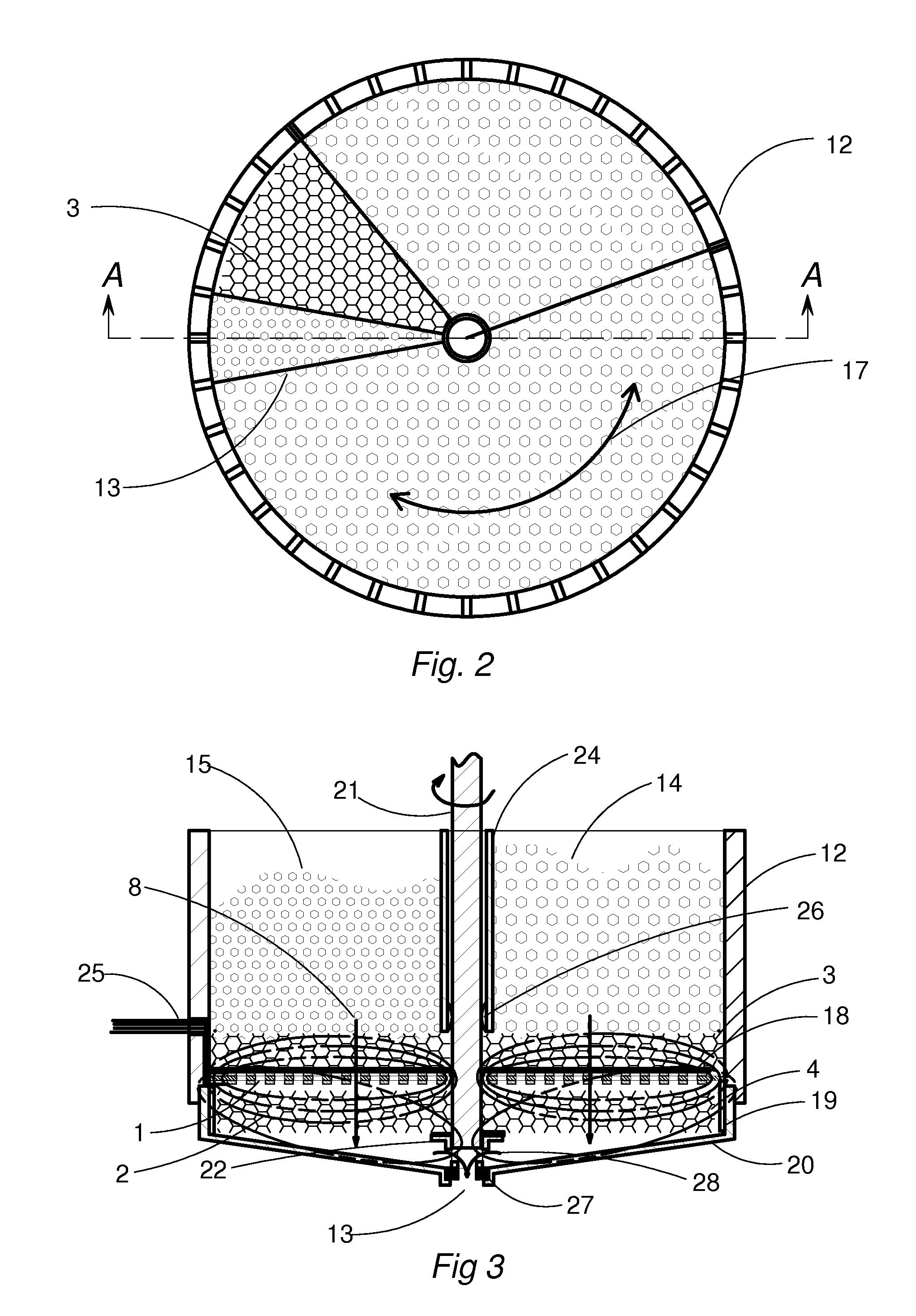
[0016]All apparatus described in this invention include items as shown in partial cross section FIG. 1. These items are placed in the order shown in close proximity to and substantially parallel to the energy-inducing coil 1. The magnetic field 2 of the inductor coil 1 intercepts the primarily susceptor 3 and secondarily rotating susceptor 4 to transform the electrical energy to heat in the form of resistive losses. Thermoplastic solid materials 5 in a particulate form are placed in contact with the heat susceptor 3. Solid materials 5 in contact with the primary surface 6 of the susceptor 3 will rise in temperature by heat conduction. As the melting thermoplastic materials 5 viscosity reduces, with added thermal conduction from the passages 7 of the susceptor 3, it flows in the direction of arrow 8. The efficient transfer of uniform energy to the susceptor 3 will enable the melting material to migrate through a defined plurality of passages 7 in susceptor 3 to its opposite face by g...


PUM

PropertyMeasurementUnit
residency timeaaaaaaaaaa
temperaturesaaaaaaaaaa
thermoplasticaaaaaaaaaa

Abstract

Multiple solid materials are introduced to a mixing vessel in defined proportion. They are melted by an electromagnetic induction heated susceptor and mixed simultaneously by the shearing action at the melt face of a second rotating susceptor. Material compounding takes place at the application site. Varying the physical structure of the susceptor or multiple susceptors processes materials of differing initial melt viscosity and particle size. Non-melting particulate material can be included in the mix. Reactive components can be combined at the application site.

Description

CROSS-REFERENCE TO RELATED APPLICATIONS[0001]This application claims the benefits of provisional application Ser. No. 60 / 889,491 filed Feb. 12, 2007, in the United States Patent & Trademark office.FIELD OF THE INVENTION[0002]A method and apparatus is presented for melting and mixing materials at their point of application. The invention utilizes induction heated susceptors to liquefy and mix thermoplastic polymer materials and modifiers at their point of application.BACKGROUND OF THE INVENTION[0003]Many solid and semisolid materials are formulated for subsequent melting and dispensing after a period of storage that requires special packaging and handling. This may include provisions for excluding exposure to the atmosphere, particulate blocking, and extended heat degradation. Additional chemical additives and containerization are required to avoid these elements in the supply of materials for subsequent melting at the application site. Expensive bulk melting equipment employing a co...

Claims


Application Information

Patent Timeline
Patent Type & Authority Applications(United States)
IPC IPC(8): H05B6/02H05B6/10
CPCH05B6/105
Inventor LASKO, BERNARD
Owner LASKO BERNARD
Why Eureka
Try Eureka