
Stochastic Scanning Apparatus Using Multiphoton Multifocal Source

a scanning apparatus and multi-photon technology, applied in the field of multi-photon microscopy imaging, can solve problems such as random scanning of foci beams, and achieve the effects of reducing overall, low background, and powerful techniqu

Inactive Publication Date: 2008-08-14
UNIVERSITY OF CHICAGO
View PDF15 Cites 50 Cited by
  • Summary
  • Abstract
  • Description
  • Claims
  • Application Information

AI Technical Summary

Benefits of technology

[0009]The experimental results obtained were supported by Monte Carlo simulations of microsphere diffusion and SS-MMM imaging. The SS-MMM approach was demonstrated for high-resolution multiparticle tracking and imaging with multiphoton excitation, which has the advantages of deep confocality, low background, and reduced overall (primarily out-of-plane) photobleaching advantages. SS-MMM may therefore be a powerful technique for tracking intracellular cargo vesicles or other particles (e.g., microspheres or nanoparticles) in vivo and / or in vitro. Additionally, the stochastic scanning method is general and adaptable to, for example, one-photon confocal descanned systems.

Problems solved by technology

Instead of driving the galvanometer with a conventional raster waveform, however, the galvanometer may be driven by a random signal source in the form of a “white noise” waveform, for example, resulting in a random scanning of the foci beams.

Method used


Image

  • Stochastic Scanning Apparatus Using Multiphoton Multifocal Source
  • Stochastic Scanning Apparatus Using Multiphoton Multifocal Source
  • Stochastic Scanning Apparatus Using Multiphoton Multifocal Source

Examples


Embodiment Construction

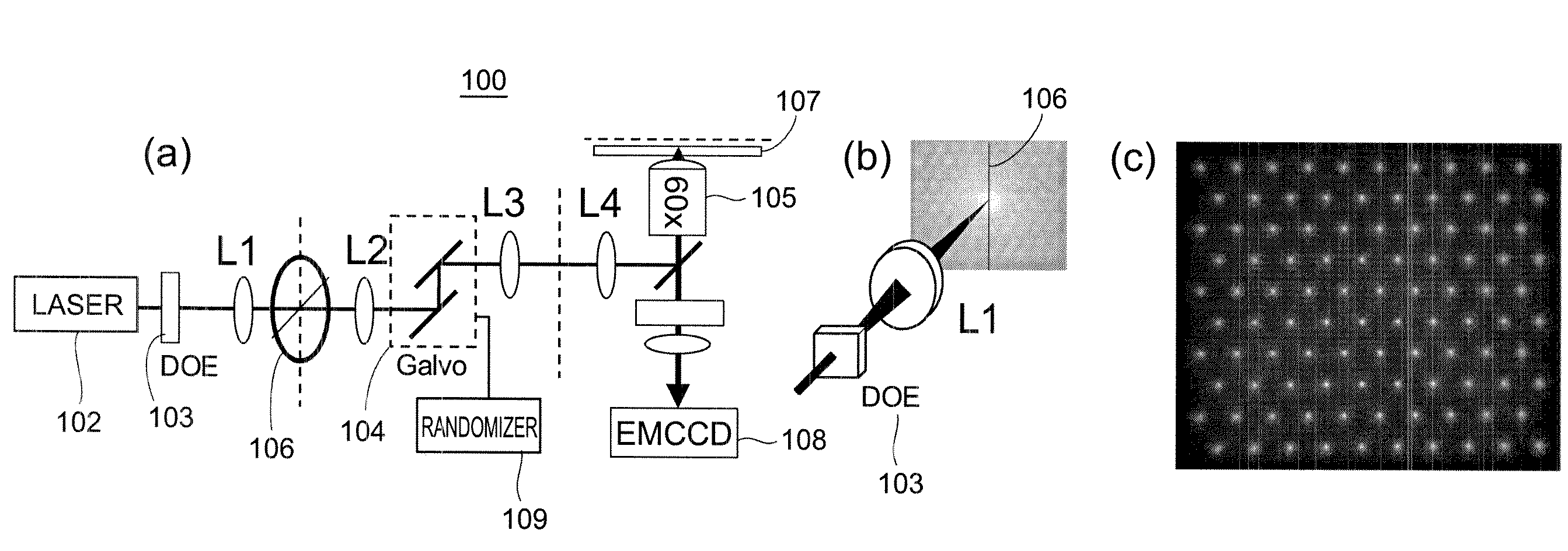
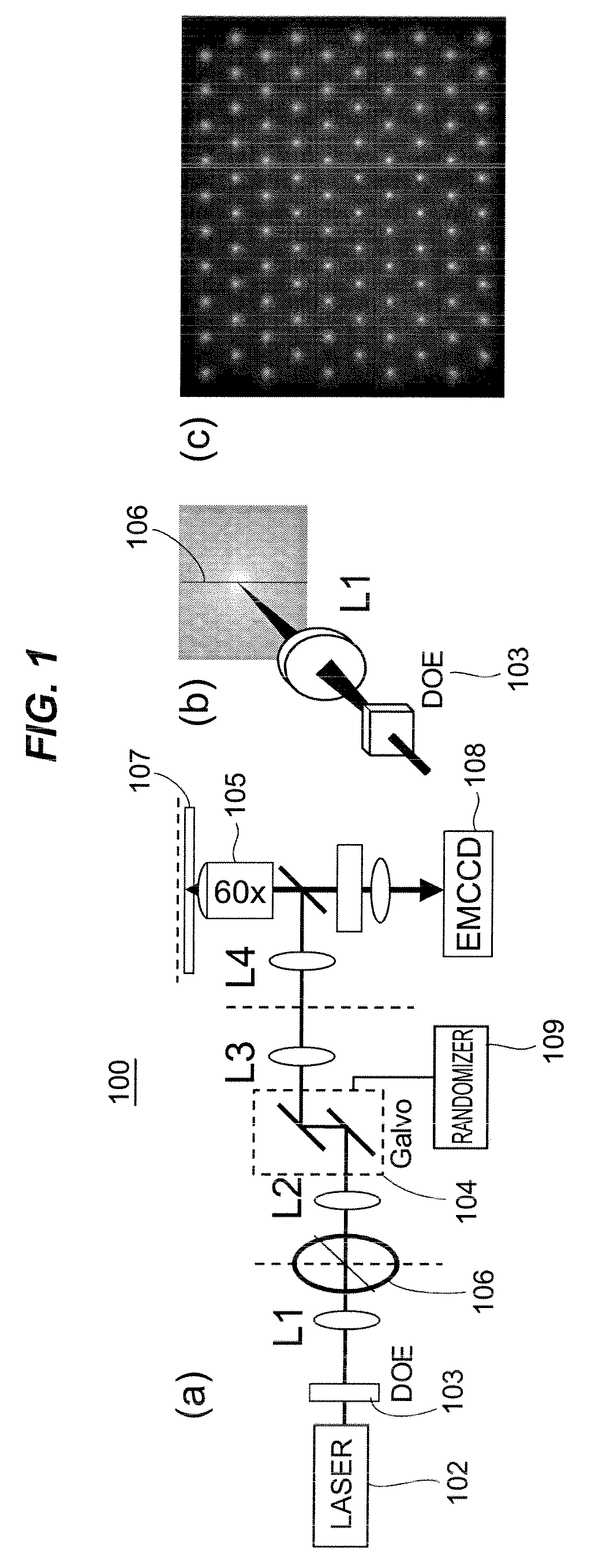
[0028]The present application demonstrates stochastic scanning multiphoton multifocal microscopy (SS-MMM) fluorescence techniques that may be used for high-speed imaging, such as of multiparticle tracking of fast dynamics over large fields of view.

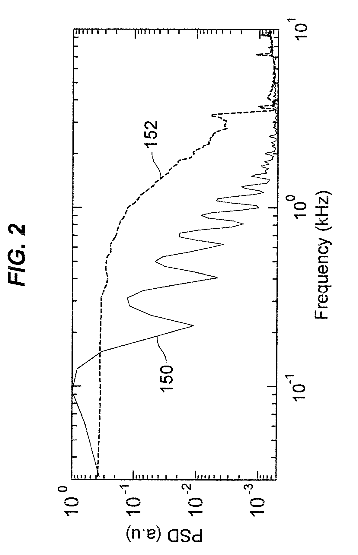
[0029]In an example, a hexagonal array of 100 excitation foci generated from a DOE is described. Stochastically scanning the array across a focal region at a sample provides enhancement in sampling bandwidth and imaging uniformity versus raster scanning. Instead of using a single frequency necessarily well below the resonant frequency, the entire optical scanner (e.g., galvanometer) bandwidth may be used (with amplitude up to 3 kHz, 10× greater than the galvanometer resonant frequency). This approach allows >100-fold more temporal information to be obtained with more uniform coverage over a sample than simply overdriving a multifocal rastering waveform on a galvanometer. The limit is rarefication of sampling, which leads to sparsity in the...


PUM


Abstract

A rapid-sampling stochastic scanning multiphoton multifocal microscopy (SS-MMM) fluorescence imaging technique enables multiparticle tracking at rates upwards of 1,000 times greater than conventional single point raster scanning. Stochastic scanning of a diffractive optical element may generate a 10×10 hexagonal array of foci with a white noise driven galvanometer to yield a scan pattern that is random yet space-filling. SS-MMM may create a more uniformly sampled image with fewer spatio-temporal artifacts than obtained by conventional or multibeam raster scanning.

Description

CROSS REFERENCE TO RELATED APPLICATIONS[0001]The benefit under 35 U.S.C. §119(e) of U.S. Provisional Patent Application Ser. No. 60 / 818,195 filed Jun. 30, 2006, is hereby claimed, and its disclosure is hereby incorporated herein by reference.SPONSORED RESEARCH[0002]The invention was made with government support under CHE-0216492 awarded by the National Science Foundation. The government has certain rights in the invention.FIELD OF THE DISCLOSURE[0003]The present disclosure relates generally to imaging and, more specifically, to multiphoton microscopy imaging of a sample.BACKGROUND OF RELATED ART[0004]Measuring transport dynamics in temporally and spatially heterogeneous nano- and micro-scale systems (e.g., cargo vesicles in vivo) requires high-resolution and high-fidelity concurrent tracking of individual objects over large fields of view. Laser scanning confocal or multiphoton fluorescence microscopies are powerful approaches for such imaging and tracking. Yet, suitable systems, pa...

Claims


Application Information

Patent Timeline
IPC IPC(8): G01N1/00G02B26/08
CPCG02B21/008G01N2015/1452
Inventor JURELLER, JUSTIN E.KIM, HEE Y.SCHERER, NORBERT F.
Owner UNIVERSITY OF CHICAGO
Learn More