Method and Device for Producing Bent Glass Bodies, and Glass Body Produced by the Method

a technology of glass body and glass body, which is applied in the direction of glass shaping apparatus, yarn, lighting and heating apparatus, etc., can solve the problems of low production cost of glass body, and achieve the effects of optimum optical properties, cost effective production, and good quality

Inactive Publication Date: 2008-08-14
SCHOTT AG
View PDF7 Cites 3 Cited by
  • Summary
  • Abstract
  • Description
  • Claims
  • Application Information

AI Technical Summary

Benefits of technology

[0011]It is accordingly an object of the invention to provide a method and device for producing bent glass bodies which overcome the above-mentioned disadvantages of the heretofore-known devices and methods of this general type and which make available an improved method with the aid of which it is possible to produce bent glass bodies cost effectively and with good quality. Furthermore, it is an object of the invention to provide a bending device with the aid of which the novel method can be carried out. Moreover, it is an object of the invention to make available a bent glass body that has optimum optical properties, in particular high transmission efficiency as well as thermal stability and chemical durability, and that it is provided with an outstanding surface quality as well as various uses of the inventive glass body. In particular, the production costs of the glass body are also to remain low.

Problems solved by technology

In particular, the production costs of the glass body are also to remain low.

Method used


Image

  • Method and Device for Producing Bent Glass Bodies, and Glass Body Produced by the Method
  • Method and Device for Producing Bent Glass Bodies, and Glass Body Produced by the Method
  • Method and Device for Producing Bent Glass Bodies, and Glass Body Produced by the Method

Examples


Embodiment Construction

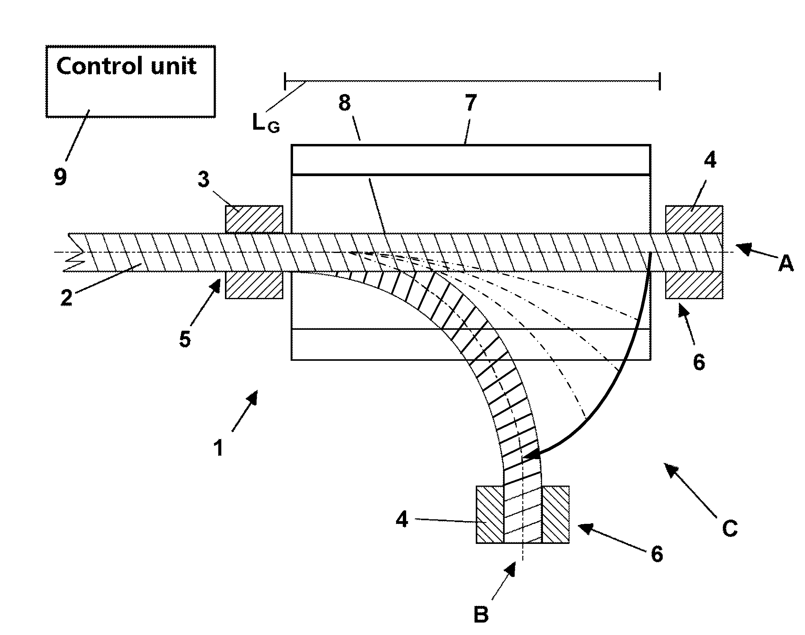
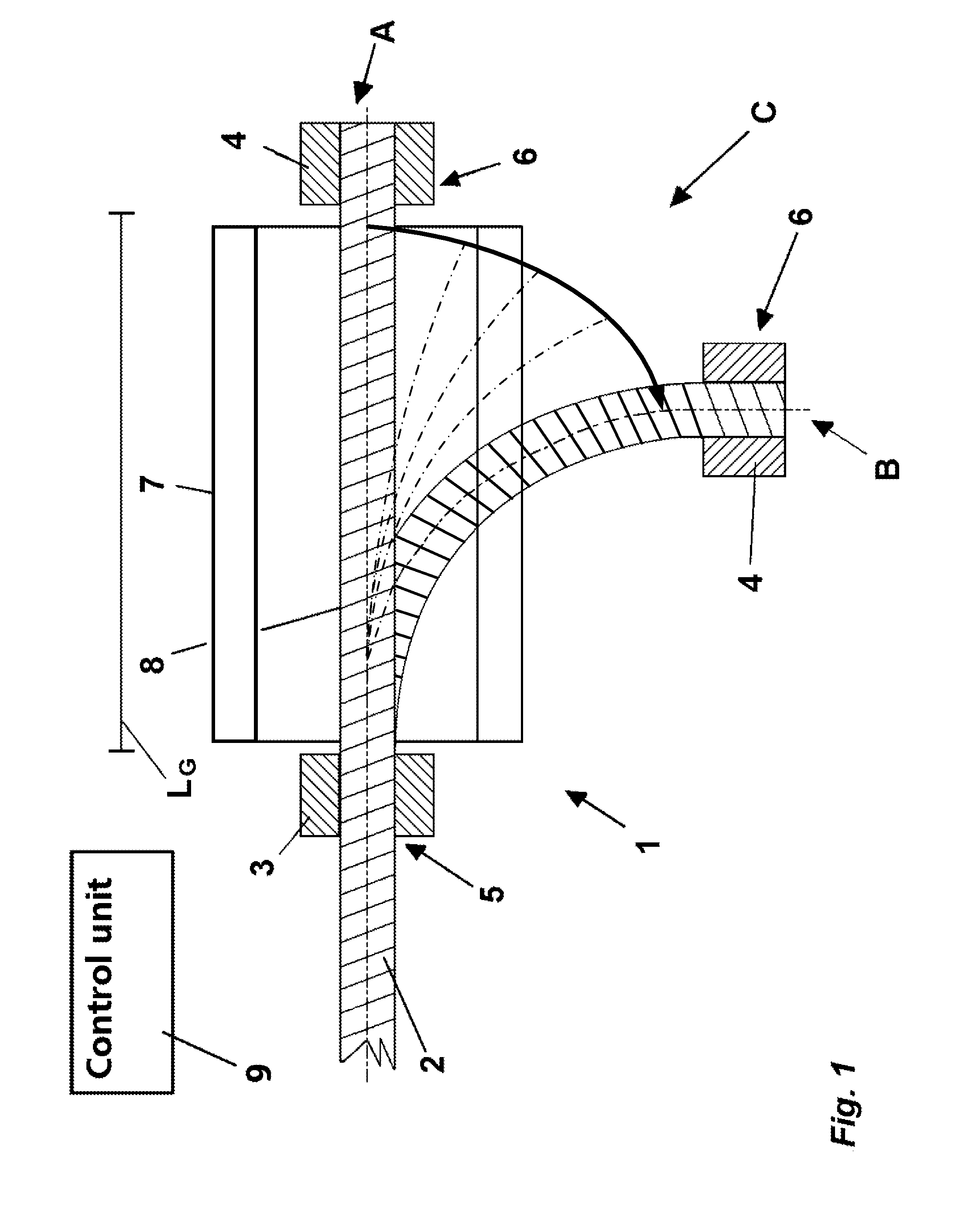
[0087]Referring now to the figures of the drawing in detail, FIG. 1 shows a schematic illustration of the inventive bending device 1, with a clamped glass blank 2 in two different states A and B. In the initial state A, the glass blank 2 is held unbent in the device 1. In the bending state B the glass blank 2 is bent.

[0088]The bending device 1 has two mutually corresponding grippers 3, 4. The grippers 3, 4 are spaced apart from one another at a predetermined spacing LG and are fastened on the glass blank 2 at corresponding clamping sites 5, 6. A bending region L0 is located between the grippers 3, 4. The bending region is selected to be smaller than the spacing distance LG between the grippers. The spacing of the grippers 3, 4 or of the clamping sites 5,6 from the bending region L0 to be heated up and / or to be bent depends on a temperature gradient of the glass material and can be prescribed as a parameter of a data processing unit (identified here as a “control unit”) 9.

[0089]The g...


PUM

PropertyMeasurementUnit
diameteraaaaaaaaaa
diameteraaaaaaaaaa
diameteraaaaaaaaaa

Abstract

A glass body with at least one curve is formed from a glass blank in bar form in a bending device for bending the glass blanks. The bending device has grippers which are movable in relation to one another. The glass blank is taken up by the grippers and clamped. Subsequently, the bending region between the grippers is heated up to a bending temperature by heating means. After that, the grippers are moved in a predetermined way, the bending region being freely bent. The advantageous effects of the invention are seen as being that any desired curves can be produced on glass blanks without requiring moulds that rely on pressing or contact. The free bending takes place without touching the surface in the heated-up bending region, so that instances of damage to the surface are avoided. This allows curved glass bodies with good optical properties to be produced.

Description

CROSS-REFERENCE TO RELATED APPLICATIONS[0001]This is a continuation, under 35 U.S.C. § 120, of copending international application No. PCT / DE2006 / 001275, filed Jul. 21, 2006, which designated the United States; this application also claims the priority, under 35 U.S.C. § 119, of German patent application No. DE 10 2005 034 962.5 and German patent application No. DE 10 2005 050 093.5, respectively filed Jul. 22, 2005 and Oct. 18, 2005; the prior applications are herewith incorporated by reference in their entirety.BACKGROUND OF THE INVENTIONField of the Invention[0002]The invention relates to a method for producing a glass body provided with at least one bend from a rod-shaped glass blank, a bending device for bending glass blanks, a bent glass body that is produced from a rod-shaped glass blank by way of the novel method, and uses of the bent glass body.[0003]Bent glass bodies are preferably used in automotive engineering as an alternative to conventional combinations of signaling l...

Claims


Application Information

Patent Timeline
Patent Type & Authority Applications(United States)
IPC IPC(8): C03B37/15C03B35/20C03B37/07B32B17/00
CPCC03B23/045C03B23/065G02B6/0005Y10T428/2938Y10T428/298Y10T428/2913Y10T428/2933Y10T428/31
Inventor CRAMER, MARTIN
Owner SCHOTT AG
Why Eureka
Try Eureka