Low loss band pass filter for RF distance telemetry pin antennas of active implantable medical devices

a technology of low loss band and filter, which is applied in the field of low loss band pass filter for rf distance telemetry pin antenna of active implantable medical devices, can solve the problems of low data transfer rate, high cost, and time-consuming to go back and interrogate the device, and recover complex stored waveforms with such a low data transfer ra

Active Publication Date: 2008-08-14
WILSON GREATBATCH LTD
View PDF75 Cites 128 Cited by
  • Summary
  • Abstract
  • Description
  • Claims
  • Application Information

AI Technical Summary

Benefits of technology

[0022]A particular challenge is the packaging of such an inductor element in a volumetric efficient and low cost method such that it becomes practical inside the very small spaces of a cardiac pacemaker. The preferred embodiments presented herein illustrate a number of novel methods to accomplish this.

Problems solved by technology

However, this is particularly problematic with the old telemetry frequencies which operated below 250 kHz.
Because of the low frequency and the modulation bandwidths associated with such low frequencies, the data transfer rates are very slow.
In other words, it is very time consuming to go back and interrogate the device and recover complex stored waveforms with such a low data transfer rate.
However, an embedded high frequency antenna simply would not work because of the highly effective electromagnetic shield formed by the titanium housing itself.
The advent of high frequency distance telemetry, however, poses a serious problem for control of electromagnetic interference.
The feedthrough terminal pins are typically connected to one or more lead wires which can undesirably act as an antenna and thus tend to collect stray electromagnetic interference (EMI) signals for transmission into the interior of the medical device.
Unfortunately, this also means that this very high frequency EMI can also directly couple to the RF distance telemetry pin antenna.
It is generally not possible to associate the ceramic feedthrough filter capacitor with the distance RF telemetry pin.
In fact, for battery efficiency reasons, the total loss on the RF distance telemetry pin circuit is limited to 1.0 to 3.0 dB.
It is also well known that once undesirable electromagnetic interference enters the inside of the implantable medical device, it can cross couple through capacitive or inductive coupling or antenna action to adjacent circuits.
In other words, once the EMI is inside the implantable medical device, it can wreak havoc by coupling to pacemaker sense circuits.
Such a scenario presents a serious dilemma for the designers of the AIMDs.
That is, it is highly desirable to have a high frequency RF distance telemetry pin, however, the control of EMI is now very problematic.
In addition, compatibility of cardiac pacemakers, implantable defibrillators and other types of active implantable medical devices with magnetic resonance imaging (MRI) and other types of hospital diagnostic equipment has become a major issue.
There have been reports of latent problems with cardiac pacemakers or other AIMDs after an MRI procedure sometimes occurring many days later.
Moreover, there are a number of recent papers that indicate that the SAR level is not entirely predictive of the heating that would be found in implanted lead wires or devices.
It is speculated that SAR level alone is not a good predictor of whether or not an implanted device or its associated lead wire system will overheat.
Most experts still conclude that MRI for the pacemaker patient should not be considered safe.
As MRI technology progresses, including higher field gradient changes over time applied to thinner tissue slices at more rapid imagery, the situation will continue to evolve and become more complex.

Method used


Image

  • Low loss band pass filter for RF distance telemetry pin antennas of active implantable medical devices
  • Low loss band pass filter for RF distance telemetry pin antennas of active implantable medical devices
  • Low loss band pass filter for RF distance telemetry pin antennas of active implantable medical devices

Examples


Embodiment Construction

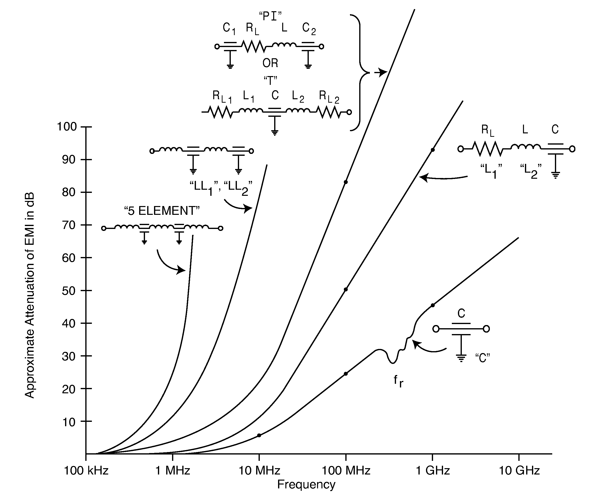
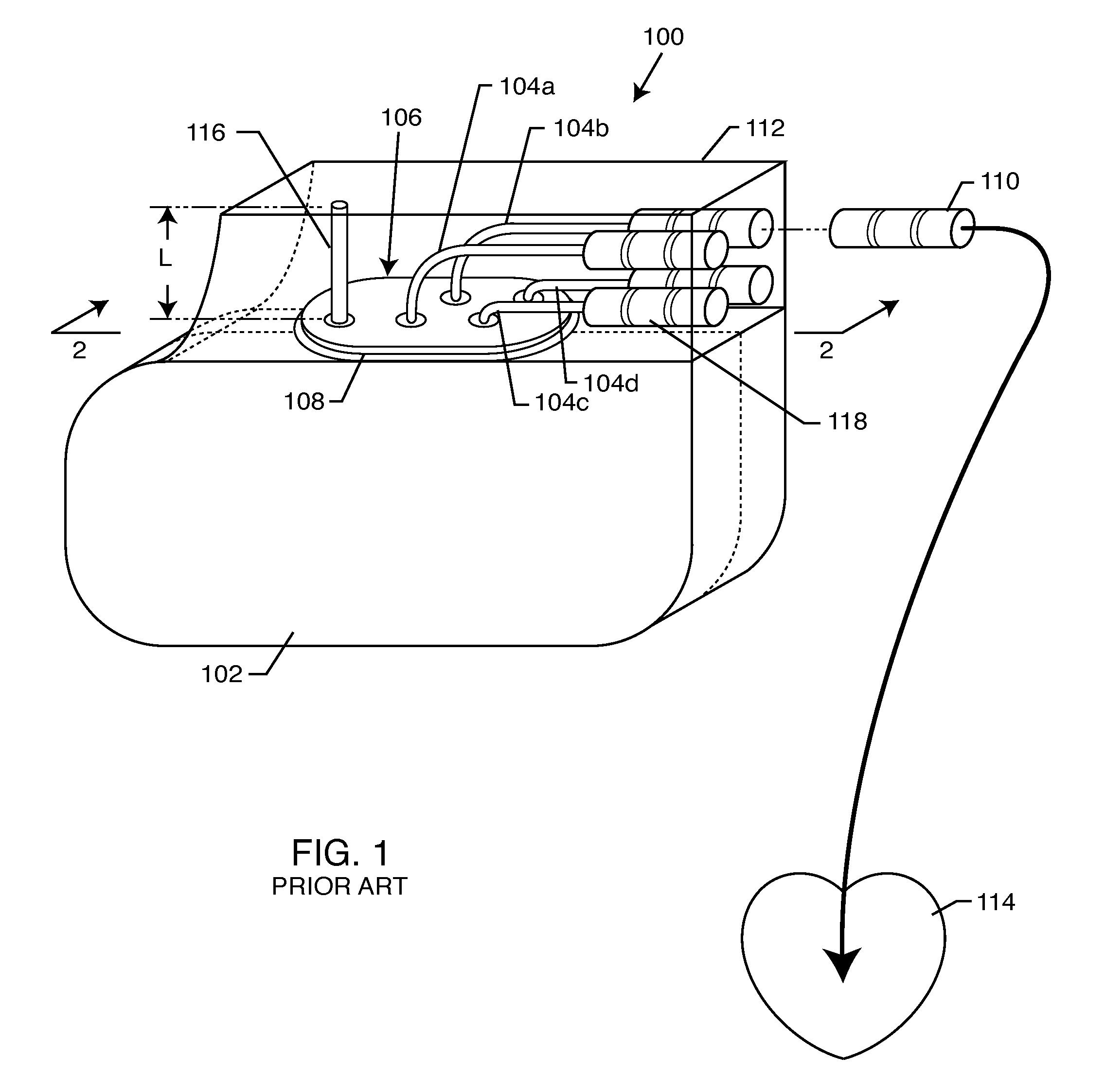
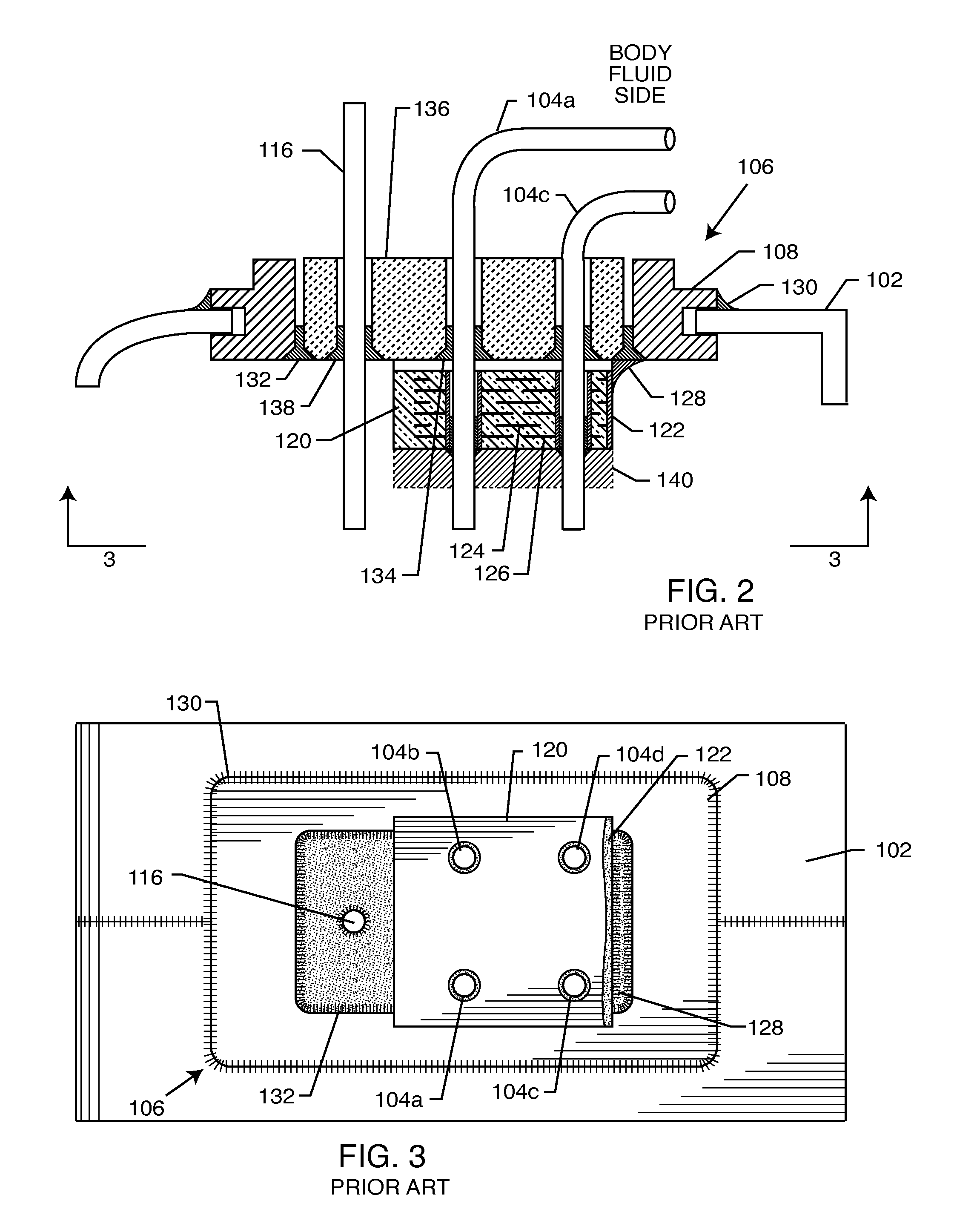
[0108]As shown in the accompanying drawings for purposes of illustration, the present invention relates to the design, fabrication, and attachment of a novel band pass filter to or adjacent to a hermetic feedthrough assembly. In one preferred form (FIGS. 10-13, 16-49 and 53-68), the band pass filter is connected between the RF telemetry pin or antenna and ground for filtering EMI separately from the RF telemetry signals. A typical band pass filter used in accordance with the present invention utilizes a capacitor and an inductor in a parallel circuit, which is in turn connected between the RF pin(s) and ground. In another preferred form (FIGS. 69-75), the band pass filter is coupled in series along the length of the RF telemetry pin for attenuating pulsed MRI frequency signals.

[0109]Several methods can be employed in the fabrication of the inductive and capacitive components, including discrete components, thin film (i.e., vapor deposition, sol gel), and thick film (i.e., screen pri...


PUM


Abstract

A hermetic terminal for an active implantable medical device (AIMD), includes an RF distance telemetry pin antenna, a capacitor conductively coupled between the antenna and a ground for the AIMD, and an inductor electrically disposed in parallel with the capacitor and conductively coupled between the antenna and a ground for the AIMD. The capacitor and the inductor form a band pass filter for attenuating electromagnetic signals through the antenna except at a selected frequency band. Values of capacitance and inductance are selected such that the band pass filter is resonant at the selected frequency band. In an alternative form, the band pass filter is coupled in series with the telemetry pin antenna for attenuating MRI signals of a selected frequency band.

Description

BACKGROUND OF THE INVENTION[0001]This invention relates generally to hermetic terminal assemblies and related methods of construction, particularly of the type used in active implantable medical devices (AIMDs) such as cardiac pacemakers, implantable cardioverter defibrillators (ICDs), biventricular pacemakers, neurostimulators, and the like. More particularly, this invention relates generally to novel EMI tank filter assemblies, particularly of the type used in active medical devices (AMDs) such as cardiac pacemakers, cardioverter defibrillators, neurostimulators, externally worn Holter monitors and the like, which decouple lead wires and / or electronic components of the medical device from undesirable electromagnetic interference (EMI) signals at a selected frequency or frequencies, such as the RF pulsed fields of Magnetic Resonance Imaging (MRI) equipment.[0002]It is well known in the prior art that electromagnetic interference (EMI) feedthrough filter capacitors are typically use...

Claims


Application Information

Patent Timeline
Patent Type & Authority Applications(United States)
IPC IPC(8): A61N1/08
CPCA61N1/05A61N1/37A61N1/3718H03H7/1775H03H1/0007H03H7/175A61N2001/086A61N1/086
Inventor STEVENSON, ROBERT A.DABNEY, WARREN S.
Owner WILSON GREATBATCH LTD
Why Eureka
Try Eureka